http://www.iaeme.com/IJMET/index.asp 290 editor@iaeme.com
International Journal of Mechanical Engineering and Technology (IJMET)
Volume 10, Issue 03, March 2019, pp. 290-297. Article ID: IJMET_10_03_030
Available online at http://www.iaeme.com/ijmet/issues.asp?JType=IJMET&VType=10&IType=3
ISSN Print: 0976-6340 and ISSN Online: 0976-6359
© IAEME Publication Scopus Indexed
PRELIMINARY DESIGN OF A MULTI-TERRAIN
TRANSPORTER
H. Adarsha
Mechanical Engineering, SET, Jain University, Kanakpura Road – 562112, Bangalore
Sunil Bhat
Mechanical Engineering, SET, Jain University, Kanakpura Road – 562112, Bangalore
Adithya Kumar
Mechanical Engineering, SET, Jain University, Kanakpura Road – 562112, Bangalore
N.G. Subramanya
Mechanical Engineering, SET, Jain University, Kanakpura Road – 562112, Bangalore
V.L.Sagar
Mechanical Engineering, SET, Jain University, Kanakpura Road – 562112, Bangalore
ABSTRACT
The transporters are required by the security forces for quick mobility to
inhospitable terrains while protecting the borders. The paper presents a preliminary
design of an all-electric multi-terrain transporter. The caterpillar design is adopted to
develop the chassis. Softwares CATIA and ANSYS are used for modelling and
analysis. Ratings of motors needed to drive the transporter are estimated. Micro-
controller unit is used to control the drive system.
Keywords: Chassis, Design, Micro-controller unit, Multi-terrain, Transporter,
Variable frequency motor
Cite this Article H. Adarsha, Sunil Bhat, Adithya Kumar, N.G. Subramanya and
V.L.Sagar, Preliminary Design of A Multi-Terrain Transporter, International Journal
of Mechanical Engineering and Technology, 10(3), 2019, pp. 290-297.
http://www.iaeme.com/IJMET/issues.asp?JType=IJMET&VType=10&IType=3
1. INTRODUCTION
Reliable and efficient transportation is the major requirement of defence forces in the present
era, however travel in each and every mountainous region of the country becomes a tedious
task due to varying topography. Countries like India have diverse geographical features that
makes it difficult for the security forces to access and protect the borders with ease.
Furthermore, the rough terrains hinder the movement of heavy artillery to the regions of high

Preliminary Design of A Multi-Terrain Transporter
http://www.iaeme.com/IJMET/index.asp 291 editor@iaeme.com
sensitivity. Thus, the need for an alternate transport arises to facilitate quick and easier
movements for providing better security to the country. Currently, the All-Terrain Vehicles
used by the security forces are good methods of transportation but these vehicles are heavy
and provide less accessibilities. Thus, better and swift vehicles with advanced features are
required to increase maneuverability in all the hostile regions. The aim of this paper is to
present the preliminary design of an all electric transporter built with capabilities of travelling
in all terrains. The vehicle is light weight and is completely powered by AC motors to run at
the speed of 25-30 km/hr with an acceleration of 5-6 m/s2. The chassis is modeled and
designed using the software tool-CATIA while considering the size of four pole induction,
high frequency motor with inverter controlled magnetic flux. Two motors of power of 25 HP
each are installed. The structural worthiness of the chassis is checked with the help of finite
element software - ANSYS.
The caterpillar design of the chassis is adopted for better inclination support and easy
movement of the transporter in rough terrains. With the calculated battery and motor
specifications, a rough run time of 3.5 to 4 hours is expected at peak loads. The concept of
variable frequency drive is introduced to allow to control the frequency of AC motor thereby
letting to set the desired acceleration and speed of the vehicle. With the calculations
performed, the vehicle is expected to run flawlessly on any terrain with gradient less than 400.
2. LITERATURE REVIEW
The work published on transporters is mainly in the form of patents. The literature review is
summarised as follows:-
A multi-terrain vertical lift transporter for lifting and transporting loads over various soil
conditions and terrain is developed [1]. The lift transporter has a laterally adjustable wheel
base to allow it to accommodate loads of varying widths. Further, the lift transporter does not
require a counter-weight as the center of gravity of the load is substantially within the wheel
base.
A multi-terrain riding board [2] includes an elongated deck mounted on a chassis, front
axle assembly pivotally coupled with the chassis and a pair of horizontal spindles that rotate
about respective vertical axes. Other constructional features of the vehicle are:- A pair of
wheels mounted for rotation about the spindles, a pair of tie rods connected between the
chassis and the spindles to transfer tilting movement of the chassis into rotation of the
spindles about the vertical axes, a rear axle coupled with the chassis and a rear wheel mounted
on the rear axle. In one embodiment, the rear axle is fixedly connected to the chassis so that
the rear wheel cambers in response to angulation of the deck. Horizontal tension springs are
connected between the spindles and the bottom portion of the chassis to help stabilize the
deck of the riding board. An engine or motor is mounted within the chassis between the front
and rear axle assemblies. The deck is connected with the chassis to permit pivotal movement
of the deck from a lowered position resting on the chassis to an elevated position thereby
allowing access to the engine.
A multi-purpose transporter [3] is developed that has a hollow container with at least one
opening located on the upper surface. Other features are:- A pair of frame rails on either side
of the hollow container with hand grips on one end and wheels on the other, a frame with
support straps extending underneath the hollow container between the pair of handles and at
least one opening on the rear of the container. The transporter is supported by the wheels and
legs attached to the frame rails. When the transporter is tipped forward, the opening is
supported above the ground by a forward support element, which includes a compartment
with a lid.

H. Adarsha, Sunil Bhat, Adithya Kumar, N.G. Subramanya and V.L.Sagar
http://www.iaeme.com/IJMET/index.asp 292 editor@iaeme.com
A personal transporter [4] is developed with improvements in motorized balancing. In one
embodiment of the invention, a transporter for carrying the payload includes the following:- A
platform for supporting the user, a ground-contacting module to which the platform is
mounted and which propels the user, a proximity detector for determining the presence of a
user, a safety switch coupled to the detector for inhibiting operation of the ground-contacting
module unless the proximity detector has determined the presence of the user, a motorized
drive arrangement coupled to the ground-contacting module for causing automatically
balanced and stationary operation of the vehicle unless the proximity detector determines the
presence of the user on the vehicle. Various other mechanisms are provided for receiving rider
input in order to direct steering of the transporter.
A device [5] is developed for transporting a human being over the ground having a surface
that may be irregular and may even include stairs. Its features are:- A ground-contacting
module movably attached to the support. The orientation of the ground-contacting module
defines fore-aft with lateral planes intersecting one another at a vertical. The support and the
ground-contacting module are components of an assembly. A motorized drive mounted to the
assembly and coupled to the ground-contacting module causes locomotion of the assembly.
Finally, the embodiment has a control loop in which the motorized drive is included for
dynamically enhancing stability in the fore-aft plane by operation of the motorized drive in
connection with the ground-contacting module. The ground contacting module is realized as
a pair of ground-contacting members laterally disposed with respect to one another. The
ground-contacting members are wheels. Alternatively, each ground-contacting member may
include a cluster of wheels.
A multi-wheel transporter vehicle [6] of the straddle-type comprising first, second, third
and fourth vertically extending corner upright members is developed. Each corner upright
further comprises a wheel assembly at the lower end and first drive means to control one or
more of said wheel assemblies in either a normal or lateral direction. A longitudinally
extending endless conveyor platform assembly includes second drive means for selectively
defining a linear motion in the longitudinal direction for conveyor between said uprights.
A wheeled transporter [7] attachable to a multi-ton cargo container for lifting and
lowering said container and moving same over the land is developed. The transporter includes
separate transporter units attachable to each end of the container for building a trailer unit.
Each unit is structured to permit high wheel travel for improved operation over rough terrain.
A multi-terrain amphibious vehicle [8] adapted for travel across surfaces of various type
and attributes is developed. The vehicle includes a chassis assembly which extends in a
longitudinal direction, a plurality of propulsion members rotatably coupled to the chassis
assembly for propelling the vehicle across a given surface and a control mechanism for
controlling the rotational velocities and phases of the propulsion members.
A cart [9] is developed for one or two hikers to transport their backpacks. The cart has a
single pneumatic tire mounted on a wheel with a double elongated aluminum tubular frame
including support braces and rubber padded angular pack brackets enclosing the wheel. Easily
adjustable and removable front and rear pairs of handles permit the hikers to direct, propel
and balance the cart. The wheel is spring-mounted to the frame by means of double concentric
steel tubes, the outer one containing a compression spring. A stretched nylon mesh covers the
frame to keep pack straps from interfering with the wheel. An accurate mileage counter is
mounted to the load angular bracket. The belt is connected to the hub of the wheel.
It is observed from the literature survey that the results of the transporter capable of
travelling in hostile terrains are not exclusively reported. Therefore, the aim of this paper is to
present the preliminary design of a transporter built with capabilities of travelling in all
terrains.

Preliminary Design of A Multi-Terrain Transporter
http://www.iaeme.com/IJMET/index.asp 293 editor@iaeme.com
3. DESIGN PROCESS
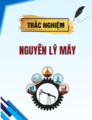
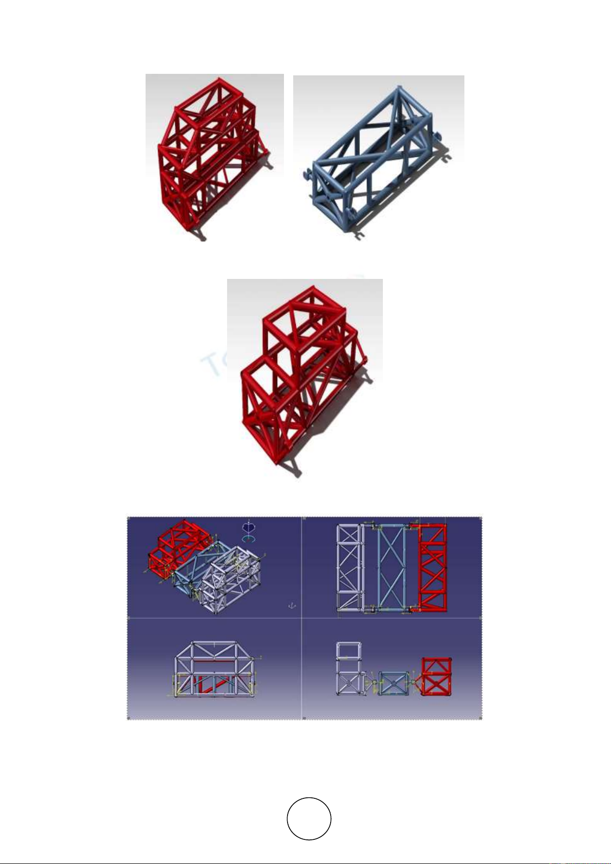
3a. Chassis
The chassis forms the main structure of the transporter vehicle that is meant to sustain the
loads. Refer Fig. 1 to Fig. 3. The chassis of the present vehicle is of tubular type that
comprises the front, middle and rear units. Each unit is designed and modelled with the aid of
solid modelling software-CATIA. The units are constructed of A36 steel that is available in
different forms namely rectangular bar, square bar, circular rod, channels, angles and beams.
Individual bars and rods are welded to make the chassis units. A36 has excellent weld
properties with good ductility that allows it to bend more readily than other steels. Its yield
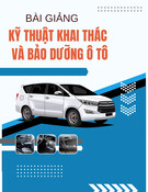
strength is 250 MPa with high % elongation of 20. Refer Fig. 4 for assembled chassis with all
the units. The caterpillar motion is ensured by units pivoted or connected by joints with each
other to allow the upward lateral movements of the units without excessively stressing the
chassis.
Structural integrity of the assembled chassis is checked with the help of finite element
(FE) analysis software-ANSYS. Refer Fig. 5 to Fig. 7. The number of elements and nodes in
each part of the chassis are equal to 14876 and 51612 respectively. Linear tetrahedron
elements are used in meshing. The modulus of elasticity and poisson’s ratio of 2x10⁵ MPa and
0.3 respectively are used in the analysis. The static load of 250 kg is applied over the model.
Acceleration and gradient loads are also entered in the software. All the connecting nodes are
suitably constrained. The stresses at critical sections of each unit are found to be well within
the limits.
3b. Rating of propulsion motors
The preliminary design calculations of the motor for the vehicle weight (including payload) of
250 kg and maximum velocity of 30 km/h are consolidated as follows:-
i) Rolling resistance = Weight * Co-efficient of rolling friction
Rolling resistance = 250 * 9.81 *0.025= 61.3 N
ii) The Gradient resistance (GR) for different angles of terrain inclination is obtained as
For ɸ= 0
GR = 250 * 9.81 *sin(0) = 0
For ɸ= 20o
GR= 250 * 9.81 *sin(20) = 838.8 N
For ɸ= 400
GR= 250 * 9.81 *sin(40) = 1576.4 N
iii) Acceleration Force = m*a
m= 250 kg
H. Adarsha, Sunil Bhat, Adithya Kumar, N.G. Subramanya and V.L.Sagar
http://www.iaeme.com/IJMET/index.asp 294 editor@iaeme.com
Figure. 1 Front unit Figure. 2 Middle unit
Figure. 3 Rear unit
Figure. 4 Assembled chassis


![Đề thi Công nghệ tạo hình dụng cụ năm 2020-2021 - Đại học Bách Khoa Hà Nội (Đề 4) [Kèm đáp án]](https://cdn.tailieu.vn/images/document/thumbnail/2023/20230130/phuong62310/135x160/3451675040869.jpg)


![Bài tập môn Cơ sở thiết kế máy [năm] [mới nhất]](https://cdn.tailieu.vn/images/document/thumbnail/2025/20251008/ltgaming1192005@gmail.com/135x160/26601759980842.jpg)

![Tài liệu huấn luyện An toàn lao động ngành Hàn điện, Hàn hơi [chuẩn nhất]](https://cdn.tailieu.vn/images/document/thumbnail/2025/20250925/kimphuong1001/135x160/93631758785751.jpg)