
CHAPTER 3
Centrifugal Systems
FEW PEOPLE realize the importance of the refrigeration
specialist in this age of aerospace weapons systems. For
them, refrigeration has nothing to do with launching a
missile and reaching the moon. However, we know that
without control of the environment of a launch complex
the military goals of defense and space conquest would
never be achieved.
2. The centrifugal refrigeration system is often
used in such weapons systems as Titan, Bomarc, and
SAGE. In this chapter we will discuss the operation of
this system, the complete refrigeration cycle, each
component of the unit, and the general maintenance
requirements.
9. Refrigeration Cycle
1. The centrifugal system uses the same general
type of compression refrigeration cycle used on other
mechanical systems. Its features are:
•A centrifugal compressor of two or more stages.
•A low-pressure refrigerant known as Refrigerant-
11. Approximately 1200 pounds of refrigerant are
required for fully charging a centrifugal machine.
2. An economizer in the liquid return from the
condenser to the evaporator acts as the expansion device.
You can compare the economizer to the high side float
(metering device) used on older model refrigerators. The
use of this piece of equipment reduces the horsepower
required per ton of refrigeration cycle. This increase in
efficiency is made possible by using a multistage
turbocompressor and piping the flash gas to the second
stage.
3. A schematic of the centrifugal cycle is shown in
figure 41. We will begin the cycle at the evaporator.
The chilled water flowing through the tubes is warmer
than the refrigerant in the shell surrounding the tubes,
and heat flows from the chilled water to the refrigerant.
This heat evaporates the refrigerant at a temperature
corresponding to the pressure in the evaporator.
4. The refrigerant vapors are drawn from the
evaporator shell into the suction inlet of the compressor.
The suction vapors are partially compressed by the first-
stage impeller and join the flash gas vapor coming from
the economizer at the second-stage impeller inlet. The
refrigerant gas discharged by the compressor condenses
on the outside of the condenser tubes by giving up heat
through the condenser tubes to the cooler condenser
water. The condensing temperature corresponds to the
operating pressure in the condenser.
5. The liquefied refrigerant drains from the
condenser shell down through an inside conduit into the
condenser float chamber. The rising refrigerant level in
this chamber opens the float valve and allows the liquid
to pass into the economizer chamber. The pressure in
the economizer chamber is approximately halfway
between the condensing and evaporating pressures:
consequently, enough of the warm liquid refrigerant
evaporates to cool the remainder to the lower
temperature corresponding to the lower pressure in the
economizer chamber. This evaporation takes place by
rapid "flashing" into gas as the liquid refrigerant passes
through the float valve and the conduit leading into the
economizer chamber. The flashed vapors pass through
eliminator baffles and a conduit to the suction side of the
second stage of the compressor.
6. The cooled liquid then flows into the
economizer float chamber located below the condenser
float chamber. The rising level in the economizer float
chamber opens the float valve and allows the liquid
refrigerant to pass into the bottom of the cooler. Since
the evaporator pressure is lower than the economizer
pressure, some of the liquid is evaporated (flashed) to
cool the remainder to the operating temperature of the
evaporator. These vapors pass up through the liquid
refrigerant to the compressor suction. The remaining
liquid serves as a reserve for the refrigerant continually
being evaporated by the chilled water. The cycle is thus
complete.
7. Now that you understand the complete
refrigeration
46
Simpo PDF Merge and Split Unregistered Version - http://www.simpopdf.com
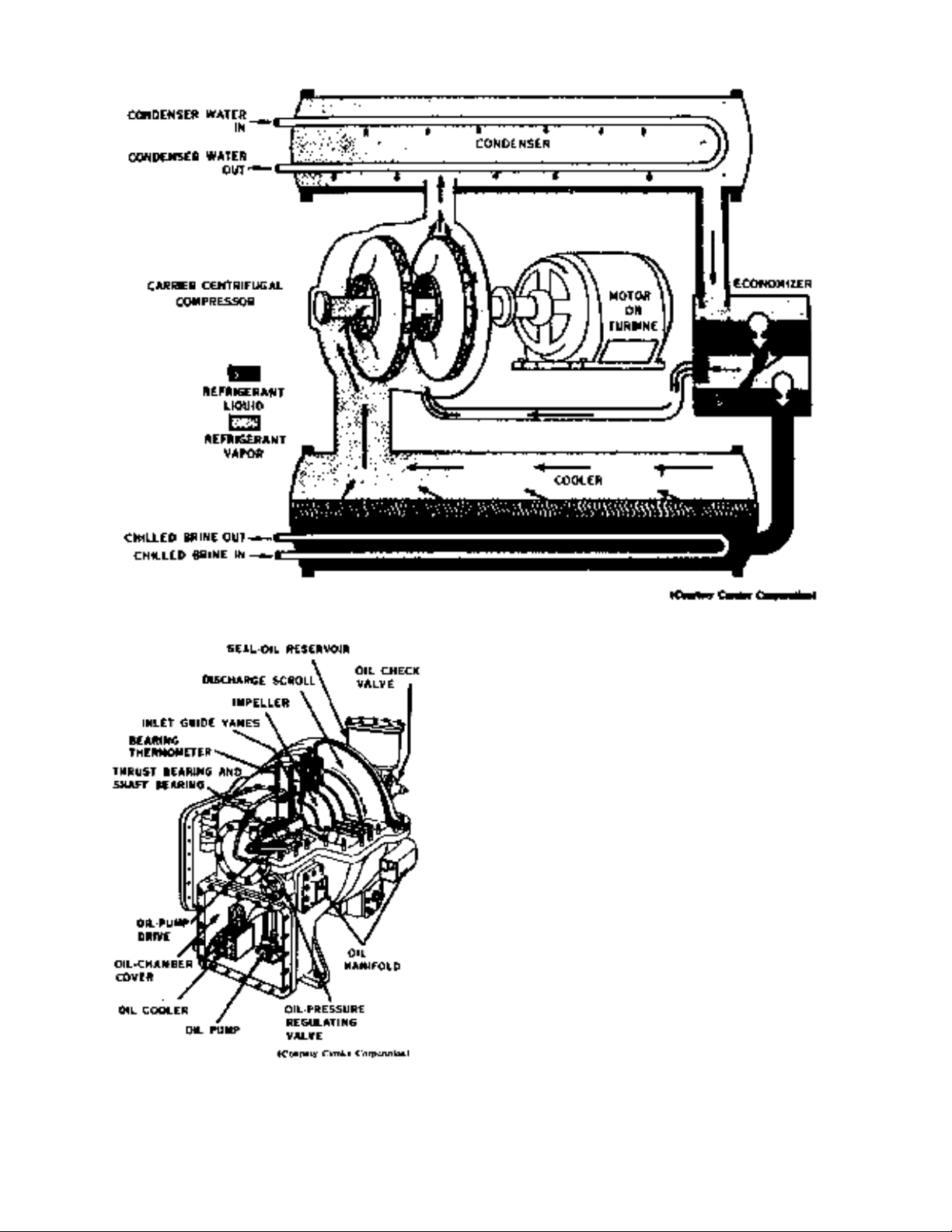
Figure 41. Centrifugal cycle.
Figure 42. Compressor cutaway.
cycle, let us study the compressor in more detail.
10. Centrifugal Compressor
1. A cutaway view of the compressor is shown in
figure 42. The easiest way to understand centrifugal
compressor operation is to think of a centrifugal fan.
Like the fan, the compressor takes in gas at the end (in
line with the shaft) and whirls it at a high speed. The
high-velocity gas leaving the impellers is converted to a
pressure greater than the inlet. At normal speed, with
R-11, the suction temperature is 65° F. below the
temperature of condensation. At maximum speed, the
compressor will produce a suction temperature of
approximately 85° F. below the condensing temperature
of R-11. Changing the speed of the compressor varies
the suction temperature.
2. The compressor casing and the various
stationary passages inside the compressor shaft are made
of hard steel with keyways provided for each impeller.
The impellers are of the built-up type. The hub disc and
cover are machined steel forgings. The blading is sheet
steel formed to curve backward with respect to the
direction of rotation and is riveted to the hubs and
covers. After assembly, the wheels are given a hot-
dipped lead coating to reduce corrosion damage. The
rotor
47
Simpo PDF Merge and Split Unregistered Version - http://www.simpopdf.com

Simpo PDF Merge and Split Unregistered Version - http://www.simpopdf.com
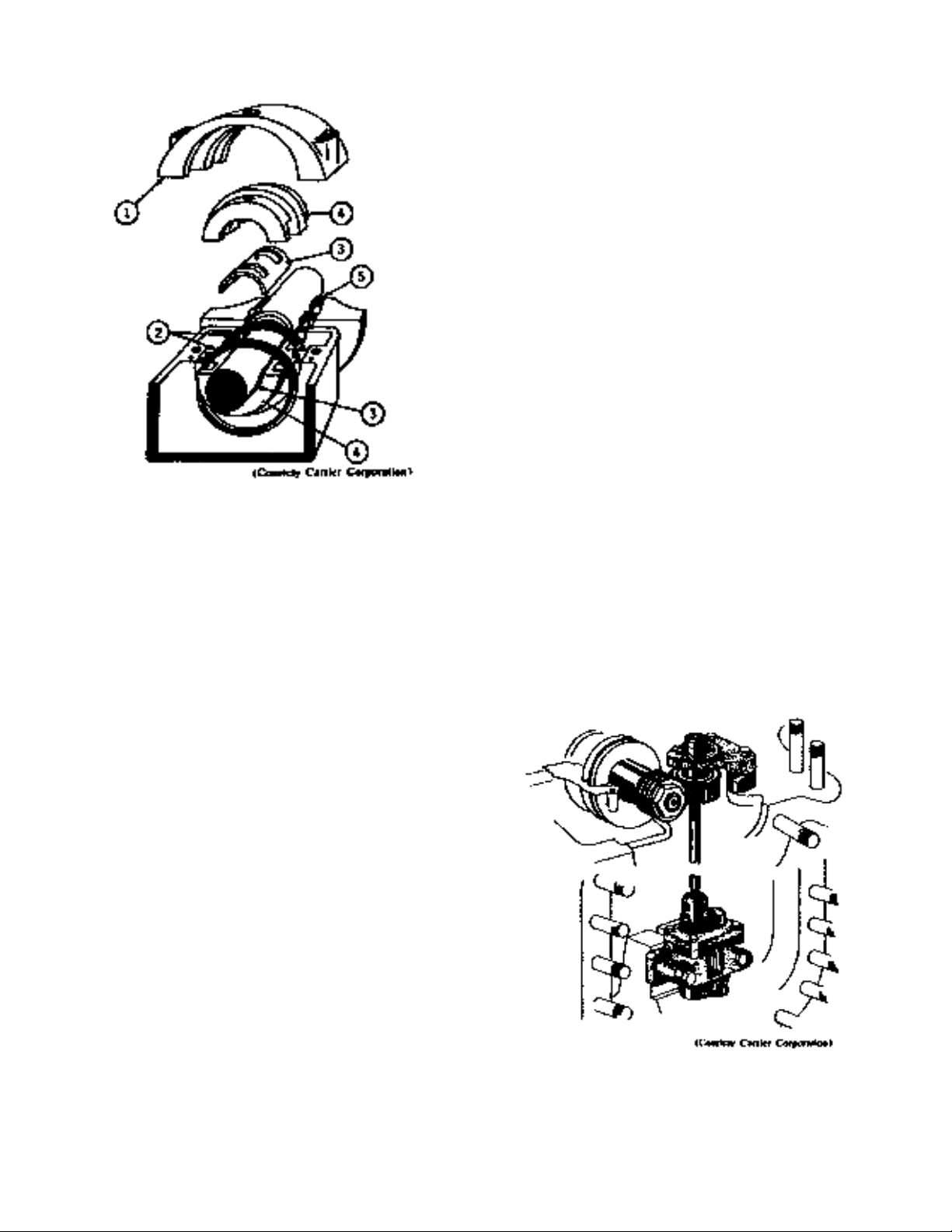
Figure 43. Bearing assembly.
assembly, consisting of the shaft and impellers, runs in
two sleeve type bearings.
3. In figure 43 a thermometer is inserted in top of
each bearing cover (1) for indicating temperature. Each
bearing also has two large oil rings (2) to insure
lubrication. The upper and lower bearing liners (3) are
held in place by the upper and lower bearing retainers (4).
4. Brass labyrinths (5) between stages and at the
ends of the casing restrict the flow of gas between stages
and between the compressor casing and bearing
chambers.
5. In operation, the pressure differential across each
impeller produces an axial thrust toward the suction end
of the compressor. This thrust is supported by a
"kingsbury" thrust bearing at the suction end of the shaft.
6. Compressor Lubricating System. The entire
oiling system is housed within the compressor casing and
the oil is circulated through cored opening, drilled pages,
and fixed copper fines. This eliminates all of the usual
external lines and their danger of possible rupture,
damage, or leakage. All of the oil for the lubricating
system is circulated by a helical gear pump, shown in
figure 44, which is submerged in the oil reservoir. The
simple, positive drive insures ample oil for pressure
lubricating and cooling all journal bearings, thrust
bearings, and seal surfaces. The reservoir which houses
the oil pump is an integral part of the compressor casing
and is accessible through a cover plate on the end of the
compressor. Circulating water cooling coils are fitted to
the cover plate to maintain proper oil temperature.
7. In general, the lubricating system (shown
schematically in fig. 45) consists of the gear type oil
pump, driven from the main compressor shaft and
supplying oil through various connections and passages
for the thrust bearing, the two shaft bearings, the oil
pump worm gear drive, and for the shaft seal-with the
necessary gauges and control valves to permit the system
to operate automatically.
8. The oil pressure or feed circuits are as follows,
according to figure 45:
•When the compressor starts, the pump (1) starts
to circulate oil, which is supplied first entirely to the
thrust bearing (3).
•After passing through the thrust bearing, the
oiling system divides into two paths known as "A" circuit
and "B" circuit.
9. In the first path, the oil flows through the
strainer (29) and the proper orifices to the pump gear (2)
and to the rear shaft journal bearing (4). Since the
thrust, rear journal bearing, and worm drive for the oil
pump are all located above the oil pump chamber, the
return oil merely drops back into the pump chamber
from these parts.
10. In the second path, oil flows through the check
valve (5) and filter (7) to actuate the shaft seal (8) and
supply the front shaft journal bearing (9). Since part of
the oil passes out through the front of the seal to
atmospheric pressure, various valves are required in the
supply lines as well as in the lines returning oil to the
pump chamber. The check valve (5) does not open
during compressor startup until the pump pressure
reaches 8 p.s.i.g. After the valve (5) opens, the flow of
oil is as described previously. If the seal oil reservoir (6)
is not full, a small part of the oil passes through the
orifice (28) to fill the reservoir. Oil under pressure to the
seal
Figure 44. Compressor oil pump.
48
Simpo PDF Merge and Split Unregistered Version - http://www.simpopdf.com
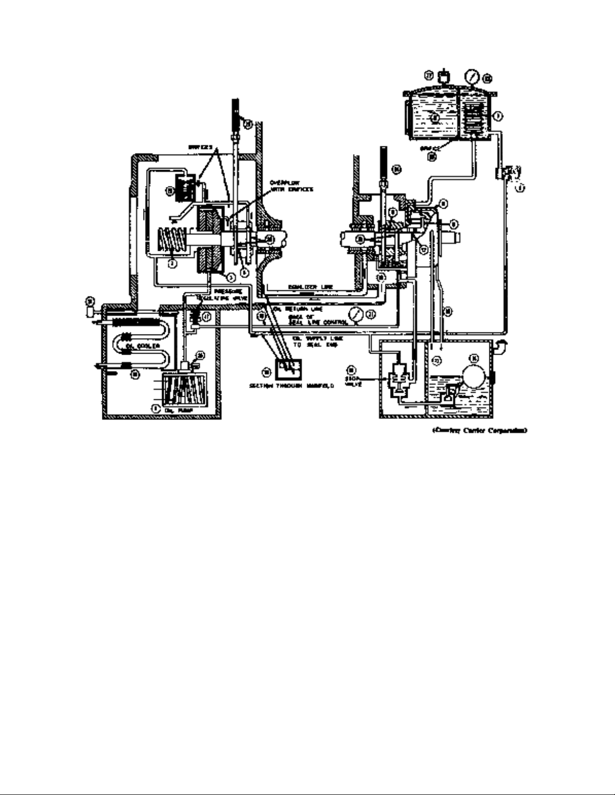
Figure 45. Compressor oil system schematic.
expands the seal bellows to move the stationary seal back
against its stop, allowing the oil to pass through the seal
in two directions: (1) inside the compressor and (2) to
the atmospheric side of the shaft seal.
11. The oil passing to the compressor (vacuum) side
of the seal flows to the front journal bearing (9), through
two small holes in the inner floating seal ring (12) -which
is located in the seal housing--to prevent unnecessary
flow of oil from the vacuum side of the seal. The
bearing overflow drops to the bottom of the bearing
chamber (10), draining back to the oil pump chamber
through the proper passage in the manifold (18).
12. The oil passing to the atmosphere is restricted by
floating rings between the stationary seal and rotating seal
hubs and between the housing cover and the rotating seal
hub. Most of it passes directly to the atmospheric float
chamber (13). The water-jacketed seal housing cover
(11) cools this oil and minimizes the refrigerant loss from
it. A small amount of oil passes the seal rings and is
returned to the atmospheric float chamber (13) through a
connection (30). From the float chamber, the oil goes
through the automatic oil stop valve (16), up to the
bearing chamber (10), and returns through the manifold
to the oil pump chamber along with the oil overflow
from the front bearing. Oil returns from the atmospheric
float chamber since the pressure in the bearing chamber
is always below atmospheric. This pressure, being
equalized with the compressor suction through the rear
shaft labyrinth, is always a vacuum during operation.
From the bearing chamber, the oil flows by gravity
through the manifold (18), to the oil pump chamber.
The automatic stop valve (16) is provided to prevent flow
of refrigerant vapor from the machine in case the
pressure inside the machine during shutdown rises above
atmospheric. The valve is set to open at approximately 8
pounds and is actuated by an oil pressure line taken from
the oil pump discharge and, therefore, opens immediately
after the compressor is started. Valve 16 also prevents
outside air from entering the machine when the machine
pressure is below atmospheric. This valve is necessary
because the atmospheric float valve (14) is designed for
level control only and is not a stop valve. Valve 17 is
49
Simpo PDF Merge and Split Unregistered Version - http://www.simpopdf.com
![Báo cáo tác động xăng dầu quý I/2018 [Mới nhất]](https://cdn.tailieu.vn/images/document/thumbnail/2019/20191001/johnluong1998/135x160/8611569904340.jpg)


![Thiết bị phản ứng trong công nghiệp hóa dầu [mới nhất]](https://cdn.tailieu.vn/images/document/thumbnail/2015/20151211/ntchung8894/135x160/5641449829003.jpg)


![Tài liệu học tập Thí nghiệm xử lý chất thải 1 (Chuyên ngành Kỹ thuật môi trường) [Mới nhất]](https://cdn.tailieu.vn/images/document/thumbnail/2026/20260512/hoatulip0906/135x160/94081778724718.jpg)

![Thiết bị phản ứng trong công nghiệp hóa dầu: Tài liệu [mô tả/hướng dẫn/kinh nghiệm]](https://cdn.tailieu.vn/images/document/thumbnail/2026/20260512/vispacex_27/135x160/2261778666802.jpg)


%20--%3e%3cdefs%3e%3cstyle%3e%20.st0%20{%20fill:%20%23fff;%20}%20.st1%20{%20fill:%20%237800fa;%20}%20%3c/style%3e%3c/defs%3e%3cpath%20class='st1'%20d='M117.78,12.18H43.11c2.9,3.47,4.65,7.94,4.65,12.82,0,5.6-2.3,10.66-6.01,14.29h76.02l7.22-13.56-7.22-13.56Z'/%3e%3cg%3e%3cpath%20class='st0'%20d='M53.58,26.17h-.59v-1.46h.59v-4.96h2.83c1.78,0,2.67.94,2.67,2.82v5.76c0,1.87-.89,2.81-2.67,2.81h-2.83v-4.96ZM55.36,21.37v3.34h1.1v1.46h-1.1v3.34h1.01c.61,0,.91-.37.91-1.1v-5.93c0-.74-.3-1.1-.91-1.1h-1.01Z'/%3e%3cpath%20class='st0'%20d='M65.99,31.14h-1.8l-.31-2.07h-2.19l-.31,2.07h-1.64l1.82-11.39h2.62l1.82,11.39ZM65.28,18.04c-.25.46-.51.77-.75.94-.21.15-.47.22-.79.22-.26,0-.57-.07-.92-.22l-.38-.15c-.14-.05-.26-.07-.37-.07-.3,0-.53.18-.71.54l-.91-.68c.25-.46.51-.77.75-.94.21-.14.48-.21.79-.21.26,0,.57.07.92.21l.38.15c.14.05.26.07.37.07.3,0,.53-.18.71-.54l.91.68ZM61.91,27.52h1.73l-.87-5.76-.87,5.76Z'/%3e%3cpath%20class='st0'%20d='M74.53,26.89v1.52c0,1.91-.89,2.86-2.67,2.86s-2.67-.95-2.67-2.86v-5.93c0-1.91.89-2.86,2.67-2.86s2.67.95,2.67,2.86v1.11h-1.69v-1.22c0-.75-.31-1.12-.93-1.12s-.93.37-.93,1.12v6.15c0,.74.31,1.11.93,1.11s.93-.37.93-1.11v-1.63h1.69Z'/%3e%3cpath%20class='st0'%20d='M81.4,31.14h-1.8l-.31-2.07h-2.19l-.31,2.07h-1.64l1.82-11.39h2.62l1.82,11.39ZM75.9,19.2l1.52-1.91h1.71l1.51,1.91h-1.61l-.76-.95-.75.95h-1.61ZM77.32,27.52h1.73l-.87-5.76-.87,5.76ZM83.1,15.99l-1.76,1.91h-1.26l1.17-1.91h1.86Z'/%3e%3cpath%20class='st0'%20d='M84.86,19.75c1.78,0,2.67.94,2.67,2.82v1.48c0,1.87-.89,2.81-2.67,2.81h-.85v4.28h-1.79v-11.39h2.64ZM84.01,21.37v3.86h.85c.58,0,.87-.36.87-1.08v-1.71c0-.71-.29-1.07-.87-1.07h-.85Z'/%3e%3cpath%20class='st0'%20d='M93.51,19.75c1.78,0,2.67.94,2.67,2.82v1.48c0,1.87-.89,2.81-2.67,2.81h-.85v4.28h-1.79v-11.39h2.64ZM92.66,21.37v3.86h.85c.58,0,.87-.36.87-1.08v-1.71c0-.71-.29-1.07-.87-1.07h-.85Z'/%3e%3cpath%20class='st0'%20d='M98.8,31.14h-1.79v-11.39h1.79v4.88h2.03v-4.88h1.83v11.39h-1.83v-4.88h-2.03v4.88Z'/%3e%3cpath%20class='st0'%20d='M105.36,24.55h2.46v1.62h-2.46v3.34h3.09v1.63h-4.88v-11.39h4.88v1.63h-3.09v3.18ZM108.17,17.29l-1.76,1.91h-1.26l1.17-1.91h1.86Z'/%3e%3cpath%20class='st0'%20d='M112.2,19.75c1.78,0,2.67.94,2.67,2.82v1.48c0,1.87-.89,2.81-2.67,2.81h-.85v4.28h-1.79v-11.39h2.64ZM111.35,21.37v3.86h.85c.58,0,.87-.36.87-1.08v-1.71c0-.71-.29-1.07-.87-1.07h-.85Z'/%3e%3c/g%3e%3ccircle%20class='st1'%20cx='25'%20cy='25'%20r='20'/%3e%3cpath%20class='st0'%20d='M32.78,19.27c2.92,0,4.43,2.55,5.28,5.33l.71,2.17c.14.38-.33.75-.71.75h-5.61c.19-.33.24-.71.09-1.08l-.75-2.45c-.43-1.32-.99-2.64-1.79-3.77.75-.57,1.65-.94,2.78-.94h0ZM25,18.38c3.25,0,4.9,2.78,5.89,5.89l.76,2.45c.14.42-.33.8-.8.8h-11.69c-.42,0-.94-.38-.8-.8l.75-2.45c.99-3.11,2.64-5.89,5.89-5.89h0ZM25,11.35c1.74,0,3.11,1.37,3.11,3.11s-1.37,3.11-3.11,3.11-3.11-1.41-3.11-3.11,1.41-3.11,3.11-3.11h0ZM17.27,19.27c1.08,0,1.98.38,2.73.94-.8,1.13-1.37,2.45-1.74,3.77l-.8,2.45c-.14.38-.05.75.09,1.08h-5.56c-.42,0-.9-.38-.75-.75l.71-2.17c.9-2.78,2.41-5.33,5.33-5.33h0ZM17.27,12.91c1.51,0,2.78,1.27,2.78,2.83s-1.27,2.83-2.78,2.83-2.83-1.27-2.83-2.83,1.27-2.83,2.83-2.83h0ZM32.78,12.91c1.56,0,2.78,1.27,2.78,2.83s-1.23,2.83-2.78,2.83-2.83-1.27-2.83-2.83,1.27-2.83,2.83-2.83h0ZM27.07,28.56v.09c0,.57-.24,1.08-.61,1.46h0v.05c-.38.33-.9.57-1.46.57s-1.08-.24-1.46-.61h0c-.38-.38-.61-.9-.61-1.46v-.09h1.41v.09c0,.19.05.38.19.47v.05c.09.09.28.19.47.19s.38-.09.47-.19v-.05c.14-.09.24-.28.24-.47t-.05-.09h1.41ZM30.99,28.56v.09c0,1.65-.66,3.16-1.74,4.24-1.08,1.08-2.59,1.79-4.24,1.79s-3.16-.71-4.24-1.79l-.05-.05c-1.04-1.08-1.7-2.55-1.7-4.2v-.09h1.41v.09c0,1.27.47,2.4,1.27,3.25h.05c.85.85,1.98,1.37,3.25,1.37s2.4-.52,3.25-1.37c.85-.8,1.37-1.98,1.37-3.25v-.09h1.37ZM34.99,28.56v.09c0,2.78-1.13,5.28-2.92,7.07-1.79,1.79-4.29,2.92-7.07,2.92s-5.23-1.13-7.07-2.92c-1.79-1.79-2.92-4.29-2.92-7.07v-.09h1.41v.09c0,2.4.94,4.53,2.5,6.08,1.56,1.56,3.72,2.5,6.08,2.5s4.52-.94,6.08-2.5c1.56-1.56,2.5-3.68,2.5-6.08v-.09h1.41Z'/%3e%3c/svg%3e)