
ISSN 1859-1531 - THE UNIVERSITY OF DANANG - JOURNAL OF SCIENCE AND TECHNOLOGY, VOL. 22, NO. 12, 2024 55
STABILIZING THE DEPTH OF A TOWED UNDERWATER VEHICLE UNDER
THE IMPACT OF RANDOM SEA WAVES
Dang Nguyen Phu1*, Tuan Vu Duc2
1Military Technical Academy, Vietnam
2University of Transport Technology, Vietnam
*Corresponding author: npdang@lqdtu.edu.vn
(Received: February 19, 2024; Revised: September 17, 2024; Accepted: September 27, 2024)
DOI: 10.31130/ud-jst.2024.054E
Abstract - Stabilizing the depth of the Towed Underwater
Vehicle (TUV) under the impact of ocean waves is the first
problem when building a control and monitoring system for TUV.
Many strategies and control methods have been proposed in
different studies, but they are not a general standard. Therefore,
this research will propose and investigate a solution for
synthesizing the control system to stabilize the TUV based on the
real interpolation method (RIM) with the main contents:
modeling the Towed cable (TC) - Underwater vehicle (UV)
system, proposing the structure of the control system and the
synthesis procedure of the regulators based on the RIM, building
a synthesis program with different TC lengths. The simulation
results show that the TUV exhibits good performance under the
impact of sea wave. They can be applied to build the experimental
models of TUV.
Key words - Towed Underwater Vehicle (TUV); Real
Interpolation Method (RIM); Transfer Function (TF); Object with
distributed parameters; Sea wave; Control system.
1. Introduction
Nowadays, TUVs, such as exploration equipment,
seabed monitoring equipment, etc., are widely used in
ocean research because of their outstanding advantages.
The Ship - Cable - Underwater Vehicle system, in terms of
stabilizing the position of UV, is a complex system
strongly influenced by the marine environment, such as
ocean currents, wind, and especially ocean waves.
In the Towing Cable - Underwater Vehicle (TC - UV)
system, the TC is an element with distributed parameters
whose processes are described by complex equations such
as partial differential equations, integral equations,
differential-integral equations, and other forms. Therefore,
the transfer function relating to the displacement of the
cable end attached to the UV and the displacement at the
cable end attached to the winch contains not only high-
order rational fractions but also delay and transcendental
components, which have strong nonlinearity [1]:
()
()
( ) ( , , ,cos( ),sin( ), ( ), ( ),...)
As
Bs
dt
W s f s e s s s sh s ch s=
(1)
Controlling the such objects (1) is a complex scientific
problem.
The modeling and control of the TUV has been
investigated in many studies. Research [2, 3] uses the
lumped mass approximation method, while [4-6] uses
classical cable theory based on the finite element method
for modeling the towed cable. However, this method
requires dividing the cable into many segments to obtain
accurate simulation results and uses non-linear numerical
models built by decomposing the vehicle into its
constituent elements. The works [7-9] use the Absolute
Nodal Coordinate Formulation (ANCF) method for
modeling the cable dynamics. This method uses a constant
mass matrix in the equation formulation, giving more
accurate results with fewer cable segments than the finite
element method.
Modeling and estimation of random sea waves using
Gaussian white noise and shaping filter are presented in the
researches [10-13], and the works [14-17] investigated the
lurch of the ship and the influence of sea waves on the
working depth of the TUV.
Research [18] proposes a nonlinear Lyapunov-based,
adaptive output feedback control law, which stabilizes the
pitch, yaw, and depth of the TUV using a nonlinear
observer for estimating the linear velocities. [19-21]
proposed a new hydrodynamic model to study the
dynamic characteristics of TUV in different operating
modes and a PID control model for depth tracking. The
researches [22, 23] implemented a controller for
compensating the influence of sea waves in the vertical
plane for the autonomous underwater vehicle based on a
modified linear quadratic Gaussian combined with a
wave filter. In addition, there are other control methods
for stabilizing the TUV, such as adaptive control, sliding
control, feedback control based on observers, and other
approaches and studies.
The above methods have solved the problem in many
different aspects with positive results. However, they
have complicated calculation procedures and large errors
and are not a common technical standard. Therefore, this
study will propose and investigate a solution to synthesize
and calibrate the regulator using the real interpolation
method [24, 25]. This method has a simple procedure,
allowing direct manipulation of the original model (1) in
the real domain and thus reducing the amount of
calculation while preserving the specific features and
effects of the objects with distributed parameters. This
research will resolve the following main issues:
Establishing the structure diagram of the TUV control
system; Building the algorithm and synthesis program of
controllers based on real interpolation method to stabilize
the depth of TUV under the impact of random sea ocean
waves; Simulating and evaluating the synthesized system
with different cable lengths and wave levels.

56 Dang Nguyen Phu, Tuan Vu Duc
2. Problem
2.1. Modeling the Towed Underwater Vehicle (TUV)
Figure 1. General structure of the TUV control system
The general structure of the TUV control system
(Figure 1) includes the main components: the control
system, the inverter-motor, the winch - pulley, and the
system of towed cable - underwater vehicle. In which, the
TC is an element with distributed parameters, whose
processes are described by complex equations such as
partial differential equations, integral equations,
differential - integral equations and other forms.
Figure 2. Functional diagram of the TUV combined control system
(DC- Motor; RR- Pulley; CBTTT- Speed sensor of ship lurch;
CBĐS- Depth sensor of the UV; PTN- The system TC - UV;
DCD- Current regulator; DCTĐ- Speed regulator;
DCVT- position regulator; T- Winch; CBTĐ- Pulley speed
sensor; BBD- Thyristor converter; THD - Input signal)
A combined control system is often used to stabilize the
UV position. It allows adjustment of both the noise and the
displacement of the UV. This system has a functional
diagram, as shown in Figure 2. The displacement signal of
the UV is measured by the depth sensor (CBĐS) mounted
on the UV and will be transmitted to the control system via
cable.
2.1.1. Modeling the TC-UV system
To model the TC - UV system in the form of TFs, which
associate between displacement at the end of the cable
attached to the UV
( , )x L s
and traction at the cable's point
attached to the winches
(0, )Ts
with displacement at the
cable’s point attached to the winches
(0, )xs
, we’ll
consider a piece of cable as its axis coincides with the axis
Oz when impacting the traction T, z is the cable’s length
without load, y and
x y z=−
are cable’s length and its
deformation with load (Figure 3) respectively. The TC-UV
system is affected by main forces: Weight of the TC-UV
system in the water, elastic force, inertial force, frictional
force between the cable with water and the cable’s
frictional force.
Figure 3. The surveyed model of the cable´s piece and
its deformation
The vertical oscillation of the cable is described by a
system of equations [15-17]:
2
22
. . / . . / .
/ . x/ . /
T
T E F x z F x z t
T z m t x t
= +
= +
(2)
where,
T
E
- Elastic modulus of the cable,
F
- the cable
cross-section;
- friction coefficient of the cable;
m
- mass of a cable’s length per measurement unit (kg);
- the friction coefficient between the cable with water (s-1).
After performing the Laplace transform with
substitution
.
T mp
E
=
, the system of equations (2)
becomes:
2
/ . . ( , ) . . ( , )
. .(1 . ). ( , ) /
T mp
T z m s x z s s x z s
T E F s x z s z
= +
= +
(3)
Based on the calculation results in [15-17], we get the
TF, which associates between the displacement at the end
of cable attached to the UV (
( , )x L s
) with displacement at
the end of cable attached to the winches (
(0, )xs
):
( )
1
2
..
( , ) ( . ( )) . ( . ( ))
(0, ) ( )
no no
dt L L
w
m s k s
x L s
W s ch r s sh r s
x s Z s
−
+
= = +
(4)
with,
/
LLw
=
- the wave propagation time in the cable;
2
( ) ( . )(1 . ),
w w mp mp
Z s b s s s
= + +
.
wd
b m w=
- the wave
impedance (
d
m
- the mass per unit length of cable,
./
T
w E F m=
- the wave propagation speed in the cable
(m/s);
mp
- the time constant of internal friction (s);
2
( ) ( . ) / (1 . )
mp mp
r s s s s
= + +
- the fluctuation
propagation coefficient;
/
mp m
=
- the relative drag
coefficient along the cable (1/s);
no
k
- the coefficient of
water resistance due to vehicle movement;
no
m
- the mass
of UV in the water. When using a “KGP-1-20” cable and a
UV with parameters: external diameter: Φ = 23.4mm;
1.63 /m kg m=
;
4020 /w m s=
;
0.01 ;
mp s
=
1
0.05s
−
=
;

ISSN 1859-1531 - THE UNIVERSITY OF DANANG - JOURNAL OF SCIENCE AND TECHNOLOGY, VOL. 22, NO. 12, 2024 57
1800 / ; 5860
no no
k kg s m kg==
, the TF (4) will have the
form:
( )
1
2 2 2
2
0.0307 5860. 1800. 0.0307
( . ) . ( . )
4020 1 0.01 4020 1 0.01
6552.6. ( 0.0307 )(1 0.01 )
dt
L s s s s L s s
W s ch sh
ss
s s s
−
+ + +
=+
++
++
(5)
2.1.2. Modeling the impact of sea waves on TUV
The TUVs are affected by many different forces and
moments such as ocean waves, ocean currents, wind and
many other uncertain factors during operation. Sea waves
are a factor that greatly affects the stability of TUVs. Under
the influence of sea waves, the end of cable attached to the
winch will fluctuate. The vertical oscillation components
(according to the OZ axis) will affect the UV, while the
horizontal oscillation components (according to the
OX,OY axis) are ignored because of their rapid decrease
under the influence of water resistance.
The block that transforms the white noise
Nt
into a
random ocean wave
()t
is described by the TF [16]:
3
2 2 2
3.694
() ( 0.5111 0.7208)( 0.9465 1.136)( 1.974 3.425)
f
s
Ws s s s s s s
=+ + + + + +
(6)
The ship's lurch (
()
K
Xs
) caused by ocean waves is
represented by a transfer function relating the vertical
displacement at the end of cable attached to the winches (
(0, )xs
) and the wave peak
()s
[16]:
2
() (0, ) 1
() ( ) ( ) 0.866 1
K
Xs xs
Ws ss
ss
= = = ++
(7)
The influence of ocean waves on the UV is represented
by the transfer function:
( ) ( ) ( ) ( )
f dt
W s W s W s W s
=
(8)
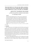
2.1.3. Modeling the winch - pulley
The structure of the winch - pulley system is shown in
Figure 4. When ignoring elastic and inertial properties, the
force on the cable between the winder and the pulley is
considered unchanged at every point of the cable. The
displacement velocity of the point attached to the winches
is determined by the expression:
(0) R L R L L
V V V V R
= + = +
(9)
where
L
R
and
L
- the radius and angular velocity of the
winch. When the winch is stationary (
0
L
V
), the pulley's
velocity (
R
V
) is the impact of ocean waves on the Winch -
Cable - Vehicle system. The winch - pulley system is
described by the TF [17]:
2
() .
L
W
R
Ws is
=
(10)
The inverter – motor are described by the TFs:
1/ 30
( ) ; ( ) . ,
11
In a M r r
In M M
In a a r a
KR
C M P
W s W s C
T s T s Js I N I
= = = =
++
(11)
with:
,
In In
KT
- gain and time constant of the inverter;
/
a a a
T L R=
- electromagnetic time constant of the motor
(
a
R
- armature resistance of the motor, -
a
L
armature
inductance of the motor);
J
- inertia moment of
the motor;
M
C
- mechanical constant of the motor;
,
rr
PN
- rated power and rated speed of the motor;
a
I
- Rated armature current of the motor.
Figure 4. Structural model of the winch - pulley system
Based on the descriptions of the TC – UV (5), the winch
– pulley (10) and the inverter – motor systems (11), the
structural diagram of the control system stabilizing the
depth of UV under the impact of ocean waves is shown in
Figure 5, where
( ), ( ), ( )
C S P
W s W s W s
- regulators of the
current, speed and position loops respectively;
()
dt
Ws
- the
TF describing the TC – UV system;
,,
C S P
K K K
- feedback
coefficients;
()
K
Xs
- the ship's lurch is caused by ocean
waves (6);
(0, ), ( , )X s X L s
- The displacements of the end
of cable attached to the winche and the UV respectively;
()
g
ht
- input signal of system). The noise
()
K
Xs
introduced into the control system through a block with a
TF
N
Ws
[17]:
( )
K
Ws
Ns
=
(12)
Figure 5. The control system stabilizing the depth of TUV under the impact of ocean waves

58 Dang Nguyen Phu, Tuan Vu Duc
2.2. Synthesis of the controllers
2.2.1. Set up the synthesis algorithm
The task is to determine the regulators
()
đc
Ws
:
1
1 1 0
1
11
...
() ... 1
mm
mm
cnn
n
đ
n
b s b s b s b
Ws a s a s a s
−
−
−
−
+ + + +
=+ + + +
(13)
and the feedback coefficient (
ht
K
) so that each loop satisfy
the condition:
yc th yc
th yc
qd qd
tt
− +
(14)
or
min
yc th yc
th
qd qd
tt
− +
→
(15)
with,
yc
- the overshoot of the desired system;
th
- the
overshoot of the synthesized system;
- the allowable
overshoot erroneous;
yc
qd
t
- the settling time of the desired
system;
min
,
th
qd qd
tt
- the settling time and the minimum
achievable settling time of the synthesized system,
respectively. In fact, when there is no regulator (13) for the
system to satisfy the condition (14), we can move to
condition (15), where the overshoot complies with the tight
limit and also the excessive time is minimal (which is still
larger than the required value). The transition from
condition (14) to (15) ensures that the synthesis problem
always has a solution without losing its generality.
Figure 6. Structure diagram of
a single-loop automatic control system
The synthesis equations corresponding to the single-
loop control system (Figure 6) will have the form:
( ) ( )
( ) ( ); ( ) 1 ( ) ( )
()
( ) ( ) ( ) ( ); ( ) 1 ( )
k k k đc đt
mm th th
đc đt ht
k
h h h mm
mm th đc đt mm k
mm ht
W s W s
W s W s W s W s W s K
Ws
W s W s W s W s W s W s K
=
+
= = −
(16)
where,
( ); ( )
kh
mm mm
W s W s
- the desired TF of the closed system
and the open system respectively;
( ); ( )
kh
th th
W s W s
- The
synthesized TFs of closed and open systems respectively.
To establish the synthesis algorithm based on the real
interpolation method (RIM) [24,25], the synthesis
equations (16) are first converted to equivalent form:
()
() ( ) ( ) ( )
( ) ( ) / ( )
k
mm
đc k
dt dt mm ht
h
đc mm đt
Ws
Ws W s W s W s K
W s W s W s
−
. (17)
The steps to solve the synthesis equations (14) based on
RIM include: Determining the feedback coefficient
ht
K
;
Finding the desired transfer function of system according
to the required criteria
,yc
yc qd
t
; Seting up and solving the
equation (17) in the real domain; Calibrating the
synthesized system.
a. Determining the feedback coefficient
ht
K
:
The feedback coefficient
ht
K
can be determined from
the static mode of the system:
1
KHH
−
(18)
with,
H
- the error in the established mode.
b. Determining the desired transfer functions:
One of the direct methods that allows determining the
desired TF
()
k
mm
Ws
based on the required quality criteria
and will be of the form [25]:
2
2
max
1
0
01
22
max
01
[ln( 1)]
16
2
( ) ; ;
9
1{[ln( 1)] }
k
mm yc
qd
yc
qd
H
sH
W s H H
s s t
H
t
−
+
= = =
++ −+
, (19)
with:
H
- settling output signal in steady state;
max
H
– the
maximum impulse response is determined from the
relation:
max 100%
yc
HH
H
−
=
.
c. Seting up and solving the synthesis equation:
To solve equation (17) based on RIM, it is first necessary
to convert it to the form in terms of real variables δ:
()
() ( ) ( ) ( )
k
mm
đc k
đt đt mm ht
W
WW W W K
−
. (20)
After that, it is necessary to find the numerical
characteristics of the functions in (20) with interpolation
nodes
( 1, ; 1)
ii m n
= = + +
according to a certain rule.
In this research, the interpolation nodes
i
are
established to coincide with the zero points of the
Chebyshev polynomials to increase the total accuracy [26]:
1, 1,
1
i
i
i
xai
x
+
==
−
(21)
with:
a
– The real parameter;
i
x
- the roots of the
equation [26]:
2
0 1 2 1 1
( ) 0
11
( ) 1; ( ) ; ( ) ;...; ( ) ( ) ( ); 1,1
24
Tx
T x T x x T x x T x xT x T x x
+−
=
= = = − = − −
(22)
Finally, the coefficients (
,
ij
ab
) of the regulator (13) are
determined by solving the system of equations:
1
1 1 0
1
11
...
() ... 1
() ; 1,
( ) ( ( )
)
mm
m i m i i
đc i nn
n i n i i
k
mm i
k
đt i đt i mm i ht
b b b b
Wa a a
Wi
W W W K
−
−
−
−
+ + + +
=+ + + +
==
−
(23)
yc
yc
qd
t

ISSN 1859-1531 - THE UNIVERSITY OF DANANG - JOURNAL OF SCIENCE AND TECHNOLOGY, VOL. 22, NO. 12, 2024 59
d. Calibrating the synthesized system.
The main ways to calibrate the received system include:
- Changing the interpolation nodes
The essence of this method is to repeat the calculation
steps with new interpolation nodes until the synthesized
system has quality criteria that satisfy the requirements
(14) or (15) (
( 1) ( ) ,1
kk
ii i
+= + =
;
()k
i
- the
interpolation nodes at the kth iteration;
( 1)k
i
+
- the
interpolation nodes at the k+1th iteration).
- Changing the desired settling time (
yc
qd
t
)
In fact, increasing/decreasing the overshoot or the
settling time will change the remaining criteria. Therefore,
we will use the settling time as an instrumental variable to
correct the overshoot. In this way, it is necessary to
determine the relationship of the overshoot
th
and the
settling time
yc
qd
t
(
()
yc
th qd
ft
=
. Then, we need to adjust the
settling time
yc
qd
t
until the received overshoot
th
satisfies
the condition (14) or (15). Frequently, the overshoot
th
will
gradually decrease as the desired settling time
yc
qd
t
increases.
- Changing the desired overshoot (
yc
)
When the overshoot of the synthesized system (
th
) is
smaller or larger than the desired value (
yc
), we can
correct it by changing the desired overshoot (
yc
) in the
neighborhood of the given overshoot. Reality shows that,
when
th yc yc
+
, it is necessary to reduce the
desired overshoot (
_ minyc yc
→
). Otherwise, the desired
overshoot should be increased (
_ maxyc yc
→
).
- Using the special weight functions (
()wt
)
Another way of calibration is to use special functions
(for example:
( ) (1 )
tt
w t e e
−−
=−
) to change the dynamic
properties of the synthesized system when changing the
interpolation nodes (
, 1, 2...
ii
=
). This allows to achieve the
required overshoot without having to change the desired
criteria
,yc
yc qd
t
.
From the above analysis, the synthesis procedure using
RIM includes the following steps:
Step 1. Choosing the regulators
( ), ( ), ( )
C S P
W s W s W s
according to (13).
Step 2. Establishing the interpolation nodes
, 1,
ii
=
from condition (21).
Step 3. Calculating the numerical characteristics,
setting up and solving the system of equations (23).
Step 4. Determining the overshoot and settling time of
the synthesized system. Checking the condition (14) or (15).
Step 5. Repeat step 2 with different interpolation nodes
, 1,
ii
=
or step 1 with different structural parameters
,mn
until obtaining a regulator that creates a corresponding
system satisfying the condition (14) or (15).
2.2.2. Synthesis of the control system stabilizing the depth
of TUV under the impact of ocean waves
In this study, it is assumed that the system consists of
separate control loops that do not influence each other.
Each loop is synthesized separately from the inner loop to
the outer loop [2]. With the structure diagram in Figure 5,
the control system includes three control loops: current,
speed and position.
Table 1. The parameters of the TC – UV system and motor – inverter
Motor D-816
Towed Cable – Underwater Vehicle
Parameters
Value
Mass of a unit length of cable
1,63( / m)m kg
Rated voltage
220
r
UV=
Outer diameter of the cable
23,4mm
Rated power
150
r
P kW=
Wave’s propagation speed in the cable
4020 /w m s
Rated speed
480
r
N rpm=
Time constant of cable’s internal friction
0,01
mp s
Maximum speed
max 1600n rpm=
Friction coefficient of cable with water
1
0,05s
Armature resistance
0.084
a
R Ohm=
Critical tension of cable
20.000 GT k
Armature current
745
a
IA=
Water’s drag coefficient caused by vehicle’s movement
1800 /
no
k kg s
Armature inductance
9.1
a
L mH=
Vehicle’s mass in the water
5860
no
m kg
Inertia moment
2
16.25J Kgm=
Thyristor converter
Maximum output voltage
Out 220UV=
Time constant
0.003( )
In
Ts=
Control voltage
10
Cont
UV=
a. Synthesis of the current loop
The synthesis equations of the current control loop
built based on the structure diagram shown in Figure 5
will have form:
a
In
C
kIn a
MC
a
In
CC
In a
1/ R
K
W (s). .
T s 1 T s 1
W (s) 1/ R
K
1 K .W (s). .
T s 1 T s 1
++
+++
(24)
where:
C
W (s)
- TF of the current regulator;
()
k
MC
Ws
- the
desired TF of the current loop. Solving the general equation
(24) is performed with the parameters of the motor and
converter given in Table 1. The TF describing the motor
and converter will have the specific form:
In M
3
22 11.9 4.012
W (s) ; W (s) .
0.1s 1 16.25s
3.10 s 1
−
==
+
+
. (25)


![Thiết kế kỹ thuật máy ép [Chuẩn Nhất]](https://cdn.tailieu.vn/images/document/thumbnail/2015/20151217/nvhbinh2011/135x160/112535267.jpg)


![Giáo trình Cấu trúc dữ liệu và giải thuật - Trường CĐ Cơ điện Hà Nội [Mới nhất]](https://cdn.tailieu.vn/images/document/thumbnail/2026/20260323/lionelmessi01/135x160/58171774381670.jpg)


![Giáo trình Tiện nâng cao (Nghề Cắt gọt kim loại, Trình độ Cao đẳng) - Trường Cao đẳng Cơ điện Hà Nội [Mới nhất]](https://cdn.tailieu.vn/images/document/thumbnail/2026/20260323/lionelmessi01/135x160/48101774403543.jpg)


