1
© ABB Group
April 17, 2015 | Slide 1
Technical Seminar
Effective solutions for motor starting and protection
ABB Low Voltage Products, HCMC
© ABB Group
April 17, 2015 | Slide 2
Effective solutions for motor starting and protection
Agenda
§9:00 – 9:15 welcome and safety briefing
§9:15 – 10:00 IEC Standard and Motor Starting Methods
§10:00 – 10:15 coffee break
§10:15 – 11:00 Softstarter - PSTX
§11:00 – 11:15 coffer break
§11:15 – 12:00 Contactor – AF Technology
§12:00 – 12:15 Q&A
© ABB Group
April 17, 2015 | Slide 3
IEC Standard &
Motor Starting Methods
© ABB Group
April 17, 2015 | Slide 4
Motor Protection
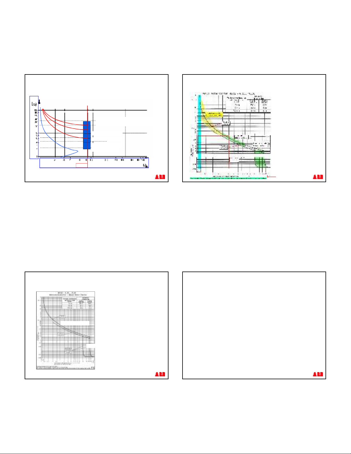
Rated short-circuit breaking capacities
§Rated short-circuit breaking capacities are defined in the
IEC 60947-2 Low-voltage switchgear and controlgear –
part 2: Circuit-breakers
§The rated short-circuit breaking capacities are stated as:
§rated ultimate short-circuit breaking capacity (Icu)
§rated service short-circuit breaking capacity (Ics)
2
© ABB Group
April 17, 2015 | Slide 5
Motor Protection
Rated ultimate short-circuit breaking capacity (Icu)
§The rated ultimate short-circuit breaking capacity of a
Manual Motor Starter is the value of the short-circuit
current the Manual Motor Starter is able to break
twice (according to the sequence of O –t –CO
cycle) at the corresponding rated operating voltage.
§The Manual Motor Starter not required to carry its
rated current after the opening and closing cycle.
© ABB Group
April 17, 2015 | Slide 6
Motor Protection
Rated service short-circuit breaking capacity (Ics)
§Test of rated service short-circuit breaking capacity
§The sequence of operations shall be: O –t –CO –t –CO
§The rated service short-circuit breaking capacity of a Manual
Motor Starter is the current value the Manual Motor Starter is
able to break three times according to a cycle of opening, pause
and closing operations (O - t - CO - t - CO) at a given rated
service voltage.
§After this cycle, the circuit-breaker must be able to carry its
rated current.
O –t –CO –t –COtest condition
The initial test setup is that there is a manual motor starter in series with breaker and the manual motor starter is in an ON position. Than the breaker is
closed on a high current onto the MMS. The MMS trips and it is in OFF/TRIP Position.
In other words the manual motor starter will trip and will close again and trip on the fault two times.
© ABB Group
April 17, 2015 | Slide 7
Manual Motor Starters MS132
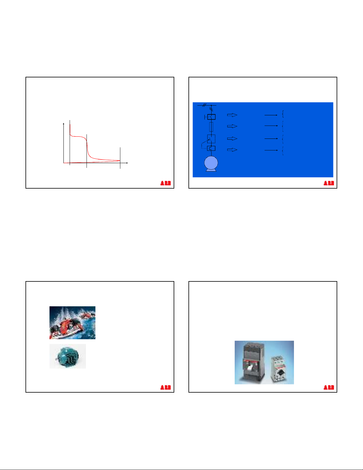
Short-circuit protection - Ratings
Ics (Rated service short-circuit breaking capacity)
Example: 25A, 400V, required rating: 50kA àno backup fuse required
until 50kA short circuit withstand
25A, 400V, required rating: 60kA àbackup fuse must be 100A
© ABB Group
April 17, 2015 | Slide 8
§< 1.05 IN= No tripping
thermal
tripping
magnetic
tripping
§1.05 Ir< IN< 1.20 tripping
within 2 hours
§14 x IN= magnetic tripping
+/-20%
Manual Motor Starters MS132
Trip Curves diagrams
3
© ABB Group
April 17, 2015 | Slide 9
Motor
curve
Ir = Setting Current
7.2 Ir
Class 10A: 2 - 10 s
Class 10: 4 - 10 s
Class 20: 6 - 20 s
Class 30: 9 - 30 s
§Standard
§Tripping curves are standardized in classes acc to
IEC 60 947-4..
Manual Motor Starters MS132
Thermal trip diagrams
© ABB Group
April 17, 2015 | Slide 10
Thermal trip curve
Magnetic trip curve
Manual Motor Starters MS132
Original Trip Curves
Standard Trip Curves
from the ABB library
or to find in Internet
Designed with simple curve
without tolerance field
© ABB Group
April 17, 2015 | Slide 11
Manual Motor Starters MS132
Trip Tolerances
Tolerances
§Thermal curve
is tested from
3 x In … 7,2 x In
with +/- 20% tolerance
§Electromagnetic curve
is tested
with +/- 20% tolerance
3
Example
Tolerance Statement
© ABB Group
April 17, 2015 | Slide 12
Motor data: Starting parameters
In accordance to the IEC 60947 - 4 - 1 standard the starting current is defined as:
Ia= 7.2 x Ie
With reference to the characteristics of the most common
motors is given a value for the typical maximum initial
starting current defined as:
Ip=12xIe
Main electrical parameters of motors
4
© ABB Group
April 17, 2015 | Slide 13
§With reference to the starting typical current waveform of the
motor (in red) the previous parameters (Ie – Ia – Isp) are
drawing as below:
Ie
Ia=7 .2xIe Ip=12xIe
I [ A]
t[s]
Main electrical parameters of motors
I e = Rated nominal current
I a = Rated starting current ( 7.2 x I n)
I p = Maximum peak inrush current
( 12 x I n)
© ABB Group
April 17, 2015 | Slide 14
Motor Protection
Coordinations in a System
Importance of Motor protection
§Assure protection of people and assets / installations
whatever the current levels may be reached:
overload or short-circuits
§Keep production running with high availability
§Reduce service costs in case of trouble
within decreasing operating durations
and replacement costs of products
§STANDARDS : IEC 60947-4-1
(Contactors and Starters)
BOTH NEEDS
LEADS TO
COORDINATION
BETWEEN THE
DIFFERENT PARTS
/ PRODUCTS OF A
MOTOR
SW ITCHGEAR.
© ABB Group
April 17, 2015 | Slide 15
PROTECT
AGAINST
OVERLOAD
ISOLATE
CONTROL
PROTECT
AGAINST
SHORT-CIRCUIT
- Disconnector
- Switch Disconnector
-Switch Fuse
-Circuit Breaker (Magnetic)
-Manual Motor Starter
- Contactor
-Thermal Overload relay
-Electronic overload relay
Motor Protection
Motor branch and coordination
M
~
3
Magnetic only circuit breaker
§It allows to have a magnetic trip threshold I3 (up to 13 times In) higher than
standard releases with value of 10 x In.
§This allows to face better the possible problems linked to the particularly high
in rush current of the motor during the first instants of its starting phase.
§To this purpose can be used the molded case circuit-breakers Tmax series
or the miniature circuit-breaker such as the MO325.
© ABB Group
April 17, 2015 | Slide 16
5
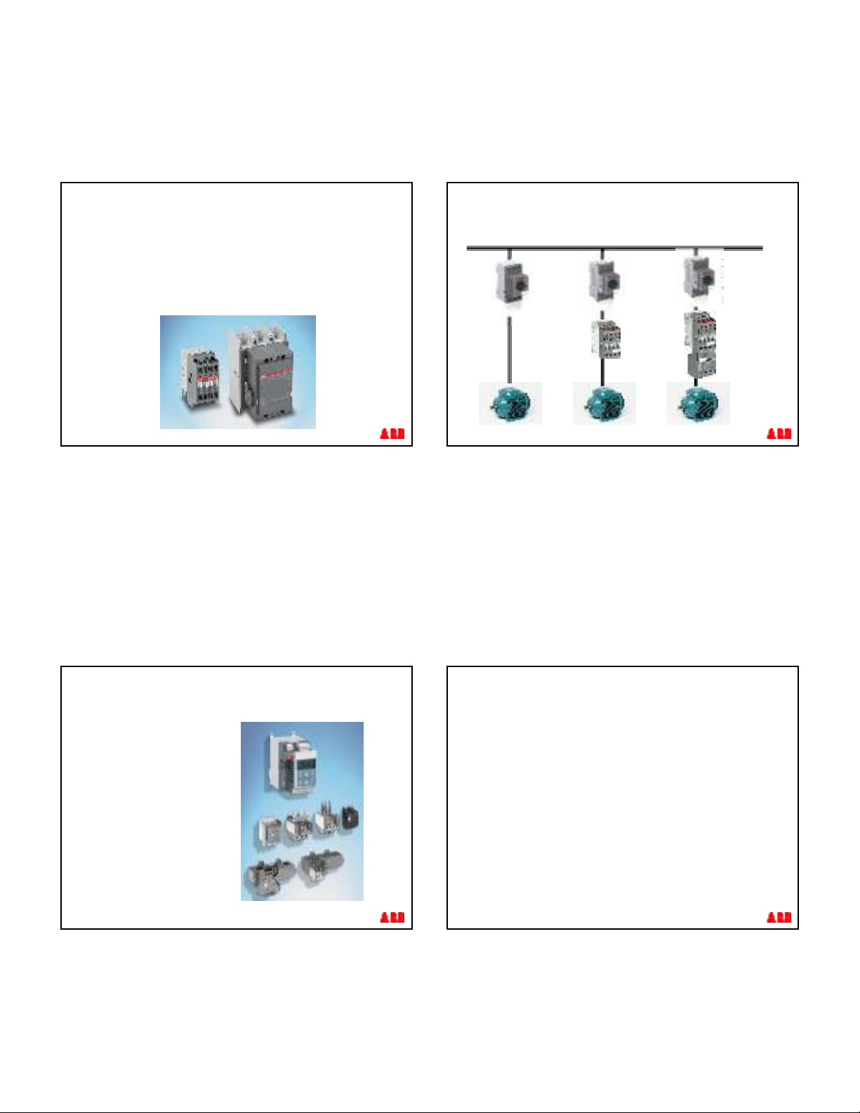
Contactor
§It is the device intended to carry out the switch on/switch off operations of the
motor under normal conditions and also to disconnect the motor from the supply
network in case of overcurrents detected by the thermal relay which commands
the tripping.
§The contactor shall be chosen so as to be suitable to carry the rated current of
the motor with reference to the category AC-3.
§Typically, the contactor allows an electrical life higher than the circuit-breaker.
© ABB Group
April 17, 2015 | Slide 17
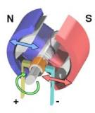
External overload relay
§It is the device intended to
realize the protection against
motor overload and it has
usually the function of
commanding the opening of
the contactor for those
overcurrents lower than the
magnetic trip threshold of the
circuit-breaker.
© ABB Group
April 17, 2015 | Slide 18
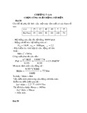
© ABB Group
April 17, 2015 | Slide 19
MO…
MMS
Short
Circuit
+
Overload
Protection
+
Switch
Overload
Protection
Short
Circuit
Protection
Control
Short
Circuit
+
Overload
Protection
Control
Motor Protection
Motor branch and coordination
© ABB Group
April 17, 2015 | Slide 20
Why to get a good coordination?
Coordination – Service Levels
Coordination type 1
find by tests
§No risk for operators or
installations
§Isolation is kept after inrush
§Before re-starting, starter
repairing is necessary
§Other apparatus than
contactor and overload
relay shall not be damaged
Coordination type 2
find by tests
§No risk for operators or
installations
§Isolation is kept after inrush
§The starter is still working
after short-circuit
§Before re-starting, a quick
inspection is sufficient
§Light welding of contacts is
allowed if they could be
easily separated (by
electrical operation or tool)


![Giáo trình CAD và ứng dụng (Phần thực hành): [Hướng dẫn chi tiết]](https://cdn.tailieu.vn/images/document/thumbnail/2026/20260305/hoatulip2026/135x160/80431773135924.jpg)

%20--%3e%3cdefs%3e%3cstyle%3e%20.st0%20{%20fill:%20%23fff;%20}%20.st1%20{%20fill:%20%237800fa;%20}%20%3c/style%3e%3c/defs%3e%3cpath%20class='st1'%20d='M117.78,12.18H43.11c2.9,3.47,4.65,7.94,4.65,12.82,0,5.6-2.3,10.66-6.01,14.29h76.02l7.22-13.56-7.22-13.56Z'/%3e%3cg%3e%3cpath%20class='st0'%20d='M53.58,26.17h-.59v-1.46h.59v-4.96h2.83c1.78,0,2.67.94,2.67,2.82v5.76c0,1.87-.89,2.81-2.67,2.81h-2.83v-4.96ZM55.36,21.37v3.34h1.1v1.46h-1.1v3.34h1.01c.61,0,.91-.37.91-1.1v-5.93c0-.74-.3-1.1-.91-1.1h-1.01Z'/%3e%3cpath%20class='st0'%20d='M65.99,31.14h-1.8l-.31-2.07h-2.19l-.31,2.07h-1.64l1.82-11.39h2.62l1.82,11.39ZM65.28,18.04c-.25.46-.51.77-.75.94-.21.15-.47.22-.79.22-.26,0-.57-.07-.92-.22l-.38-.15c-.14-.05-.26-.07-.37-.07-.3,0-.53.18-.71.54l-.91-.68c.25-.46.51-.77.75-.94.21-.14.48-.21.79-.21.26,0,.57.07.92.21l.38.15c.14.05.26.07.37.07.3,0,.53-.18.71-.54l.91.68ZM61.91,27.52h1.73l-.87-5.76-.87,5.76Z'/%3e%3cpath%20class='st0'%20d='M74.53,26.89v1.52c0,1.91-.89,2.86-2.67,2.86s-2.67-.95-2.67-2.86v-5.93c0-1.91.89-2.86,2.67-2.86s2.67.95,2.67,2.86v1.11h-1.69v-1.22c0-.75-.31-1.12-.93-1.12s-.93.37-.93,1.12v6.15c0,.74.31,1.11.93,1.11s.93-.37.93-1.11v-1.63h1.69Z'/%3e%3cpath%20class='st0'%20d='M81.4,31.14h-1.8l-.31-2.07h-2.19l-.31,2.07h-1.64l1.82-11.39h2.62l1.82,11.39ZM75.9,19.2l1.52-1.91h1.71l1.51,1.91h-1.61l-.76-.95-.75.95h-1.61ZM77.32,27.52h1.73l-.87-5.76-.87,5.76ZM83.1,15.99l-1.76,1.91h-1.26l1.17-1.91h1.86Z'/%3e%3cpath%20class='st0'%20d='M84.86,19.75c1.78,0,2.67.94,2.67,2.82v1.48c0,1.87-.89,2.81-2.67,2.81h-.85v4.28h-1.79v-11.39h2.64ZM84.01,21.37v3.86h.85c.58,0,.87-.36.87-1.08v-1.71c0-.71-.29-1.07-.87-1.07h-.85Z'/%3e%3cpath%20class='st0'%20d='M93.51,19.75c1.78,0,2.67.94,2.67,2.82v1.48c0,1.87-.89,2.81-2.67,2.81h-.85v4.28h-1.79v-11.39h2.64ZM92.66,21.37v3.86h.85c.58,0,.87-.36.87-1.08v-1.71c0-.71-.29-1.07-.87-1.07h-.85Z'/%3e%3cpath%20class='st0'%20d='M98.8,31.14h-1.79v-11.39h1.79v4.88h2.03v-4.88h1.83v11.39h-1.83v-4.88h-2.03v4.88Z'/%3e%3cpath%20class='st0'%20d='M105.36,24.55h2.46v1.62h-2.46v3.34h3.09v1.63h-4.88v-11.39h4.88v1.63h-3.09v3.18ZM108.17,17.29l-1.76,1.91h-1.26l1.17-1.91h1.86Z'/%3e%3cpath%20class='st0'%20d='M112.2,19.75c1.78,0,2.67.94,2.67,2.82v1.48c0,1.87-.89,2.81-2.67,2.81h-.85v4.28h-1.79v-11.39h2.64ZM111.35,21.37v3.86h.85c.58,0,.87-.36.87-1.08v-1.71c0-.71-.29-1.07-.87-1.07h-.85Z'/%3e%3c/g%3e%3ccircle%20class='st1'%20cx='25'%20cy='25'%20r='20'/%3e%3cpath%20class='st0'%20d='M32.78,19.27c2.92,0,4.43,2.55,5.28,5.33l.71,2.17c.14.38-.33.75-.71.75h-5.61c.19-.33.24-.71.09-1.08l-.75-2.45c-.43-1.32-.99-2.64-1.79-3.77.75-.57,1.65-.94,2.78-.94h0ZM25,18.38c3.25,0,4.9,2.78,5.89,5.89l.76,2.45c.14.42-.33.8-.8.8h-11.69c-.42,0-.94-.38-.8-.8l.75-2.45c.99-3.11,2.64-5.89,5.89-5.89h0ZM25,11.35c1.74,0,3.11,1.37,3.11,3.11s-1.37,3.11-3.11,3.11-3.11-1.41-3.11-3.11,1.41-3.11,3.11-3.11h0ZM17.27,19.27c1.08,0,1.98.38,2.73.94-.8,1.13-1.37,2.45-1.74,3.77l-.8,2.45c-.14.38-.05.75.09,1.08h-5.56c-.42,0-.9-.38-.75-.75l.71-2.17c.9-2.78,2.41-5.33,5.33-5.33h0ZM17.27,12.91c1.51,0,2.78,1.27,2.78,2.83s-1.27,2.83-2.78,2.83-2.83-1.27-2.83-2.83,1.27-2.83,2.83-2.83h0ZM32.78,12.91c1.56,0,2.78,1.27,2.78,2.83s-1.23,2.83-2.78,2.83-2.83-1.27-2.83-2.83,1.27-2.83,2.83-2.83h0ZM27.07,28.56v.09c0,.57-.24,1.08-.61,1.46h0v.05c-.38.33-.9.57-1.46.57s-1.08-.24-1.46-.61h0c-.38-.38-.61-.9-.61-1.46v-.09h1.41v.09c0,.19.05.38.19.47v.05c.09.09.28.19.47.19s.38-.09.47-.19v-.05c.14-.09.24-.28.24-.47t-.05-.09h1.41ZM30.99,28.56v.09c0,1.65-.66,3.16-1.74,4.24-1.08,1.08-2.59,1.79-4.24,1.79s-3.16-.71-4.24-1.79l-.05-.05c-1.04-1.08-1.7-2.55-1.7-4.2v-.09h1.41v.09c0,1.27.47,2.4,1.27,3.25h.05c.85.85,1.98,1.37,3.25,1.37s2.4-.52,3.25-1.37c.85-.8,1.37-1.98,1.37-3.25v-.09h1.37ZM34.99,28.56v.09c0,2.78-1.13,5.28-2.92,7.07-1.79,1.79-4.29,2.92-7.07,2.92s-5.23-1.13-7.07-2.92c-1.79-1.79-2.92-4.29-2.92-7.07v-.09h1.41v.09c0,2.4.94,4.53,2.5,6.08,1.56,1.56,3.72,2.5,6.08,2.5s4.52-.94,6.08-2.5c1.56-1.56,2.5-3.68,2.5-6.08v-.09h1.41Z'/%3e%3c/svg%3e)