
Tạp chí Khoa học và Kỹ thuật - ISSN 1859-0209
41
A NOVEL PIPE-CLIMBING FLEXIBLE ROBOT
FOR PIPE INSPECTIONS
Minh Hoan Vu1,*, Xuan Hiep Trinh1, Van Hoan Nguyen1
1Faculty of Mechanical Engineering, Le Quy Don Technical University
Abstract
For robots, crawling through curved or redirected pipe sections with different pipe diameters
to inspect and survey pipes is quite a difficult task. To solve this problem, in this article we
propose a new pipe inspection robot model that is a combination of rigid mechanical
structures with a soft body to ensure the robot moves smoothly and is flexible. The
mechanical design model of the robot includes the front radial actuator, the central axial
actuator, and the rear radial actuator. In order to assist the robot in adhering tightly to the pipe
wall and producing a fulcrum for stable movement, the front and rear actuators are made of
a rigid mechanical framework that can expand radially. The central axial actuator is the soft
body that can flow through curved pipes and expand rapidly in the axial direction when filled
with air to aid in the robot’s forward motion. The robot’s flexibility in movement is made
clear by kinematic models of mechanical structures and deformation simulations of soft
bodies. Preliminary calculations and simulation results show that this new robot design has
the potential to move flexibly and efficiently in pipes with variable diameters and diverse
configurations.
Keywords: Crawling robot; flexible robot; mechanical design; kinematic model.
1. Introduction
Robots have become an indispensable part of people’s lives. Robots replace humans
to do heavy and dangerous jobs. For instance, assessing and surveying subterranean
pipeline systems is necessary to minimize damage and repair time via early detection of
accidents and damage inside the pipeline. Over time of use, pipes are susceptible to defects
such as corrosion, stress, and aging that cause pipes to leak, crack, or break. As a result, it
is possible to slow down the decrease in business activity, which will have a significant
effect on the oil and gas industry [1, 2]. In addition, as a tiny robot can climb into chimneys
and pipes to look for survivors, pipe-climbing robots can also be utilized for search and
rescue operations [3-5]. Due to their high practicality, pipeline inspection robots have
played an important role in recent years and have become an urgent need in society.
Many pipeline inspection robots have been proposed in the past two decades based
on wheeled, caterpillar, snake, legged, worm, screw, helical drive [6], and other specific
* Corresponding author, email: hoanvm@lqdtu.edu.vn
DOI: 10.56651/lqdtu.jst.v19.n03.811

Journal of Science and Technique - Vol. 19, No. 03 (Nov. 2024)
42
structure types [7, 8]. To move through the pipeline, these robots must continuously
operate under the high pressure of the fluid flow, changing their outer diameter and
switching from horizontal crawling to vertical climbing. Basic climbing ability has been
reported in wave robots [4, 5], deep robots [9, 10], and robots that rely on friction to
climb [11, 12]. However, these robots are not designed to significantly change their
diameter to adapt to different pipe diameters, make turns along the curvature of the pipe,
or switch from horizontal crawling to vertical climbing. Snake robots [12, 13] have the
ability to alter their outward shape in order to adapt to varying pipe diameters. They can
also move forward by using several gaits while crawling through pipe branches. However,
they move forward by sliding, which consumes energy and limits their mobility. In order
to increase their outside diameter, these robots are constructed with many joints. Robots
with different moving methods are presented in [14-17], such as helical drive [15, 16] and
the two-mass inertial method [17]. The pipe-climbing robots mentioned above often have
a rigid mechanical structure. The advantages of this type of robot are high durability, good
bearing capacity, stable movement, and great accuracy in measurement and inspection
duties. This kind of robot’s drawback is that it is less flexible when navigating through
intricately shaped pipes, tiny curved angles, or pipe sections with varying diameters.
In addition, this robot often has a large size, weight, and complex mechanical structure,
so it is only suitable for moving large-diameter pipes.
In recent years, there has been a significant increase in the study and use of soft robot
structures due to their flexibility and softness. Soft robots are also widely utilized in many other
fields, particularly in the areas of harmful environment pipeline surveying and inspection, as
well as human blood vessel and intestinal examination. Soft robots are capable of operating
independently and flexibly by using highly elastic materials for the main body and moving
parts [18, 19], such as polymers, silicone rubber, or other types of soft materials [20]. Unlike
rigid manipulators, soft robots are considered to have infinite degrees of freedom because
they can deform arbitrarily [21, 22], are suitable for various complex environments, and can
interact safely with objects when they come into contact [23]. In addition, soft robots can
easily access narrow spaces, curved roads, and deformed pipes. However, the structure of
this type of robot is often made of a soft body that is easily deformed, so its bearing
capacity is small, there is less stable movement and lower energy efficiency, and its load-
carrying capacity is small, so this type of robot is often only suitable for pipes with small
diameters of a few tens of centimeters or less. The publication [24] provides a summary
of pipe-climbing robot models, which are typically designed based on either rigid or soft
body structures but not a combination of these mechanisms. This limitation restricts the
flexibility and performance of the robots. Additionally, a mix of soft and hard

Tạp chí Khoa học và Kỹ thuật - ISSN 1859-0209
43
constructions for worm-like in-pipe robots was presented in [25]. The center motion
actuator in this design is a stiff structure, whereas the robot’s front and rear actuators are
made of extremely elastic materials. The robot can only move in pipe sections with a
certain diameter because soft actuators at both ends are used to generate friction with the
pipe wall. Furthermore, the robot’s front and rear actuators exert very little force on the
tube wall, which results in a low level of stable moving capability. Additionally, this
design restricts the robot’s capacity to maneuver through curved pipes because the central
actuator is a hard structure.
Because of the drawbacks and restrictions of every kind of robot and to address the
need for more flexible movement within complex pipeline systems, it is an urgent
requirement to design a new robot model that addresses the current technical
requirements. In this article, we introduce a novel flexible robot design that combines the
strengths of both rigid and soft structures. The robot has a rigid frame structure that can
expand radially to help the robot adhere tightly to the pipe wall, and the center soft body
has the ability to flexibly stretch to help the robot move forward and adapt through
sections of curved tube. With this structure, the robot has both high rigidity and the ability
to move smoothly, stably, and flexibly in pipes with variable diameters and different
directions of movement. This is a new potential solution to using this kind of robot for
surveying and inspecting pipeline systems.
2. Design and movement of the flexible robot
2.1. Design of the flexible robot
This robot design model aims to allow the robot to move flexibly in straight pipe
segments of varying diameters. As shown in Fig. 1, the flexible robot includes a front
radial actuator (1), a central axial actuator (2), and a rear radial actuator (3). All three
actuators are driven by compressed air through air ducting (4). The front (1) and rear (3)
radial actuators of the robot will expand axially after inflation, resulting in the radial
movement of the friction plate (6) (shown in Fig. 2). The central axial actuator (2) can
expand in the axial direction and limit radial expansion after being injected with air. By
alternately inflating and deflating the three actuators, the robot will crawl forward into
the tube. As shown in Fig. 2, the construction of the front actuator and the rear actuator
are similar. The initial diameter and length of these two actuators are 73 mm and 56 mm,
respectively; the initial diameter and length of the central shaft drive are 35 mm and
80 mm, respectively (Fig. 3). The air chambers of the actuators are made of highly elastic
silicone rubber material, with a wall thickness of 2 mm. The material of the remainder
parts of the robot is steel. In particular, springs are made from carbon-steel materials. The
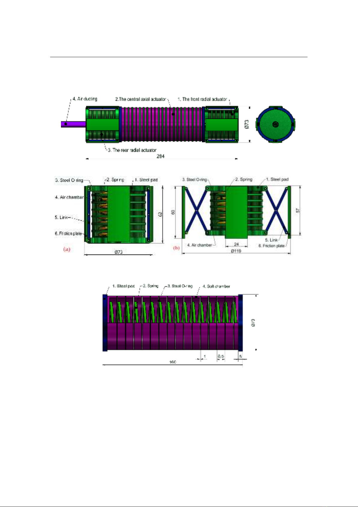
Journal of Science and Technique - Vol. 19, No. 03 (Nov. 2024)
44
robot measures about 284 mm in length and 73 mm in diameter, and its weight is about
1.85 kg, which can be estimated based on the robot’s 3D model in Inventor software (Fig. 1).
Fig. 1. The structure and size of the flexible robot.
Fig. 2. Structure of the front and rear radial actuators
a) The initial state of the radial actuator; b) The state of the radial actuator after deflation.
Fig. 3. The structure and size of the central axial actuator.
2.2. Movement of the flexible robot
Figure 4 shows the entire motion cycle of the flexible robot in the pipeline, where
Fig. 4a is the initial state of the robot and Figs. 4b - 4f are five different motion states of
the robot. At first, the rear radial actuator will be discharged, and the air chamber will
collapse under the elastic force of the spring and the pressure difference inside and outside

Tạp chí Khoa học và Kỹ thuật - ISSN 1859-0209
45
the air chamber. This movement will drive the steel pad (1), which is connected to the
friction plate (6) through the transmission links (5). The movement of the steel pad (1)
causes the friction plate (6) to open in the radial direction and press against the inner wall
of the tube, creating a stable fulcrum. Thus ensuring the robot does not move backward
when the central actuator is pumped with air (Fig. 4b). Next, the central actuator is
pumped with air, causing it to expand in the direction of the robot’s axis, pushing the
radial actuator (1) forward (Fig. 4c). Then, the front radial actuator (1) is released with
the air, and the air chamber is collapsed under the effect of spring elasticity and the
pressure difference inside and outside the air chamber. This movement causes the friction
plate (6) to move radially via the movement of the steel pad (1) (the front and rear radial
actuators operate on the exact same principle), causing the friction plate (6) to press close
to the inner wall of the tube (Fig. 4d), creating a solid fulcrum for the robot, and at the
same time, the rear radial actuator is pumped with air to narrow the diameter of the friction
plates, returning the rear radial actuator to a free state. Then, the central axial actuator is
deflated (Fig. 4e), and under the elastic force of the spring at the central actuator (2), the
rear radial actuator (3) is pulled towards the front. Finally, the rear radial actuator is released
with air, expanding the friction plates against the inner wall of the tube (Fig. 4f), and
meanwhile, the front radial actuator is brought to a relaxed state by the air pump, and the
flexible robot in the tube returns to its original state, ending one cycle of robot movement.
The robot repeats this cycle to keep it moving forward. In addition, the robot will move
backwards if the entire above process is reversed.
Fig. 4. A movement cycle of the flexible robot
(a) The initial state of the flexible robot; (b-f) Five statuses during the movement.


![Thiết kế sơ bộ robot chuyển động trong đường ống thủy lợi [chuẩn nhất]](https://cdn.tailieu.vn/images/document/thumbnail/2025/20250411/vimaito/135x160/2931744365389.jpg)


![Đề thi Kỹ thuật lập trình PLC: Tổng hợp [Năm]](https://cdn.tailieu.vn/images/document/thumbnail/2026/20260121/lionelmessi01/135x160/85491768986870.jpg)

![Đề thi cuối học kì 1 môn Máy và hệ thống điều khiển số năm 2025-2026 [Kèm đáp án chi tiết]](https://cdn.tailieu.vn/images/document/thumbnail/2025/20251117/dangnhuy09/135x160/4401768640586.jpg)


![Tự Động Hóa Thủy Khí: Nguyên Lý và Ứng Dụng [Chi Tiết]](https://cdn.tailieu.vn/images/document/thumbnail/2025/20250702/kexauxi10/135x160/27411767988161.jpg)
