30 Tran Minh Sang, Luu Duc Binh, Do Le Hung Toan, Tran Minh Thong, Pham Nguyen Quoc Huy, Vo Nhu Thanh
DESIGN AND FABRICATION OF AUTOMATIC TILT ANGLE ADJUSTMENT
DEVICE FOR PRECISION MEASUREMENT APPLICATION
Tran Minh Sang*, Luu Duc Binh, Do Le Hung Toan, Tran Minh Thong,
Pham Nguyen Quoc Huy, Vo Nhu Thanh
The University of Danang – University of Science and Technology, Vietnam
*Corresponding author: tmsang@dut.udn.vn
(Received: July 22, 2024; Revised: August 26, 2024; Accepted: September 06, 2024)
DOI: 10.31130/ud-jst.2024.338E
Abstract - This article describes the design and fabrication of an
angle tilt adjustment device that automatically adjusts the
measured surface to parallel the surface plate. The device features
a 150 mm × 150 mm worktable and enables independent tilt
adjustment of the worktable surface in the X and Y directions via
two worm-gear pairs driven by stepper motors. For high angular
resolution around the OX and OY axes, the device employs a
transmission ratio of 6781 from two motors to these axes. The
experimental results reveal that the adjusted average
nonparallelism between the measured surface and the surface
plate reaches 0.001 mm. The results indicate that the device is
fully capable of performing accurate measurements. The device
is compact, easy to carry, and low in production cost, making it
ideal for installation in small and medium mechanical workshops.
Key words - Angle tilt adjustment; worm-gear; stepper motor;
surface plate; accurate measurements
1. Introduction
The foundation of research, design, and development
in engineering activities is precise mechanical
measurement. It involves assessing various quantities that
directly affect the operation and performance of
components, devices, or processes. To be valuable, these
measurements must be accurate, certain, and reliable [1].
A mechanical detail drawing serves as a comprehensive
communication tool between the designer and the
manufacturer. It provides clear and concise information
about the part's geometry, dimensions, tolerances,
materials, and any other necessary details essential for its
production and assembly. The dimensional tolerance,
shape tolerance, and position tolerance requirements must
be carefully reviewed to ensure that the machined part
meets the specifications. The 12 geometric characteristic
symbols are classified into five categories: form, profile,
orientation, location, and runout. [2].
To measure the above geometric characteristics, a datum
feature needs to be identified. A datum feature is the actual
part surface where a datum symbol on the part drawing
references. These datum features are used to establish
imaginary axes or planes from which we can measure angles
and/or locations. There are several reasons for selecting
datum features. In some cases, they are chosen to speed up
the manufacturing process of the part. Additionally, datum
features can be functional surfaces that help the part seat,
mate, and align with other parts during assembly. The
primary datum feature, especially if it is a planar surface,
should have a large enough surface area to improve the
stability of the part during measurement [3].
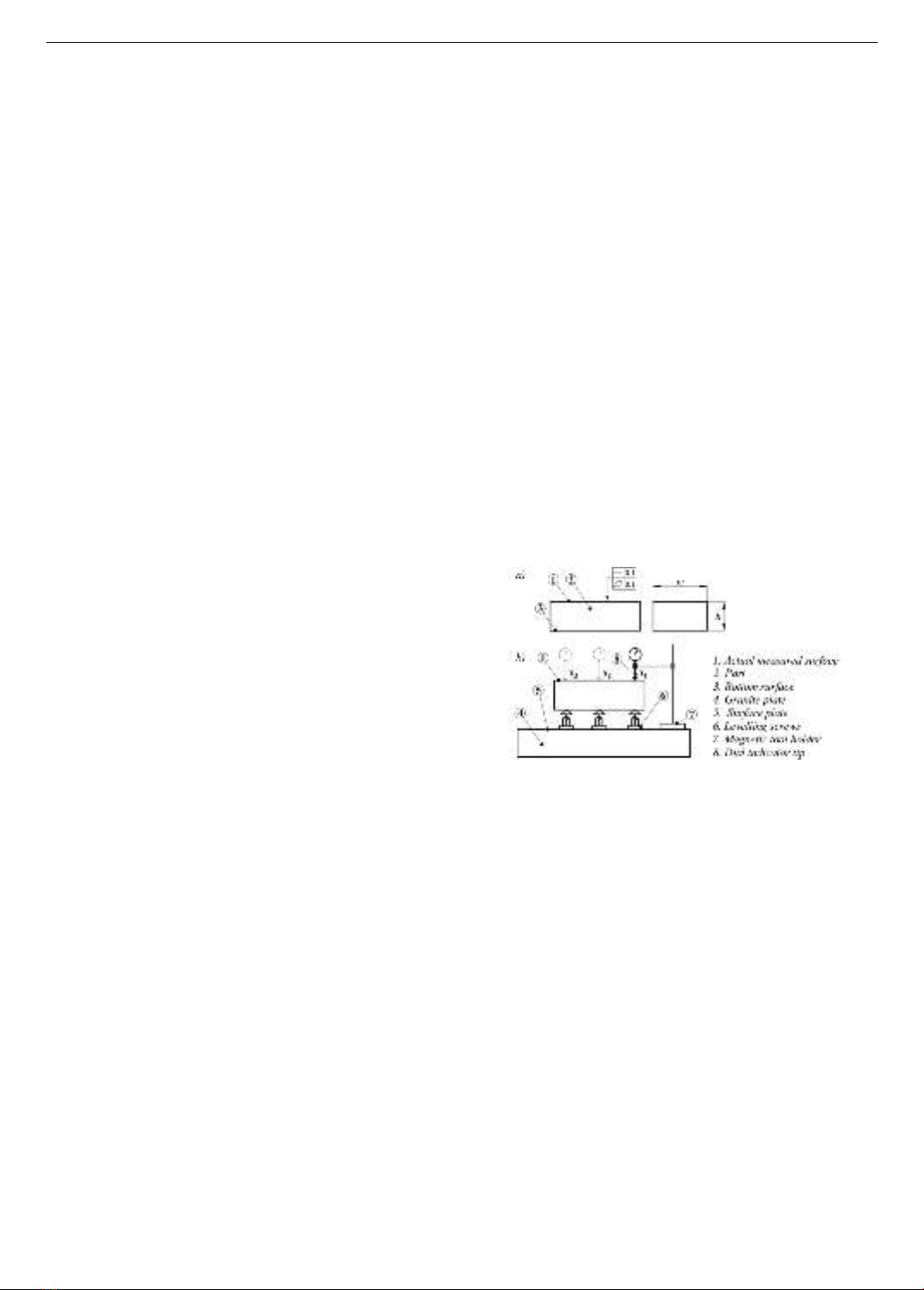
Two specific examples of measuring flatness and
straightness are shown in Figure 1a. To measure the
flatness and straightness of the actual surface (1), we first
place the bottom surface (3) of part (2) on three levelling
screws (6). The magnetic tool holder (7) is placed on the
surface plate (5), and the dial indicator tip (8) is brought
into contact with the surface to be measured (1). Next,
surface (1) is adjusted parallel to surface plate (5) (Figure
1b). Because adjusting two parallel surfaces with levelling
screws is time-consuming and requires an experienced
technician, there is an urgent need to design a device that
simplifies this process. This device eliminates the need for
levelling screws altogether.
Figure 1. Example of the preparation process for measuring
the straightness and flatness of a surface. a) Straightness and
flatness tolerance requirements; b) Adjusting the actual surface
parallel to the surface plate
Large manufacturing companies and measurement and
inspection centers often utilize a coordinate measuring
machine (CMM) to achieve high accuracy and reduce
measurement times. For example, measuring flatness and
straightness on CMM involves precisely measuring
numerous points on the actual surface and comparing them
to a perfect plane. The resulting flatness and straightness
errors quantify the surface's deviation of the surface from
ideal flatness and straightness, providing valuable insights
for quality control and precision manufacturing [4].
However, despite their outstanding advantages, the high
cost of CMM machines makes them less feasible for
investment by smaller companies or factories.
When CMM measuring machine is not used, to detect
the tilt angle around the OX and OY axes, Rajesh et al.
proposed the use of two accelerometers. These
accelerometers can sense changes in the system's angular
position in any direction. The microcontroller then scales
the detected change and outputs a corresponding angle tilt
value. However, the mechanism for adjusting this angle
ISSN 1859-1531 - THE UNIVERSITY OF DANANG - JOURNAL OF SCIENCE AND TECHNOLOGY, VOL. 22, NO. 12, 2024 31
measurement was not mentioned in their work [5]. Chen
et al. presented a new method using a double ballbar to
measure and identify all the geometric errors in a five-
axis machine tool tilt table. The method separates errors
through a novel fitting technique and verifies identified
errors with a comparison between predicted and
measured values. The identified errors are used to reduce
the ballbar installation errors [6]. In addition, many
methods for determining tilt have been proposed, such as
techniques for the precise adjustment of the tilt angle of a
radio frequency (RF) probe [7], passive radio frequency
identification (RFID) technology [8], and the use of a
physical model with three sensitive axes of
microelectromechanical system (MEMS) accelerometers
[9]. After the tilt angle is determined, a mechanical
transmission system is set up to adjust that tilt angle.
Yuliza et al. described a simple single-axis motion table
system for high-resolution tilt sensor testing. The system
uses a stepper motor with a resolution of 0.9 degrees per
step, which is lower than the requirement of some tilt
sensors; a gear system with a 50 transmission ratio was
implemented to increase its resolution to 0.018 degrees
per step [10]. Shinno et al. designed an X-Y planar motion
table system driven by linear motors for high-precision
nanomachining applications. The system utilizes eight
voice coil motors (VCMs) for precise motion control.
VCMs 1 – 4 generate push – pull forces along the X-axis,
whereas VCMs 5-8 control the Y-axis through thrust
forces. Additionally, by strategically controlling
opposing VCMs, the system can achieve minimal Z-axis
rotational adjustments to compensate for orientation
errors up to 1 𝜇𝑟𝑎𝑑 [11]. Manual goniometer stages
(stages 1-Axis or 2-Axis) manufactured by MISUMI
Group Inc. achieve a rotational resolution of 0.1 degrees
around the X- and Y-axes. Motorized goniometer stages,
on the other hand, achieve a resolution of 0.002 degrees
[12]. While Shinno's system achieves exceptional
precision through complex control, it also incurs
significantly higher manufacturing costs. MISUMI's
commercial products also have very high prices.
This study proposes an angle tilt adjustment device,
which offers a resolution comparable to that of MISUMI
device but at a lower manufacturing cost. On the other
hand, by researching, designing, and fabricating the tilt
adjustment device itself, the research team gained valuable
experience in the technologies needed for developing
accurate measurement support devices in the future.
Moving forward, the team aims to manufacture the
equipment for educational purposes and to make it
available for use in measurement tasks via small and
medium-sized mechanical workshops.
2. Device design
2.1. Adjusting principle
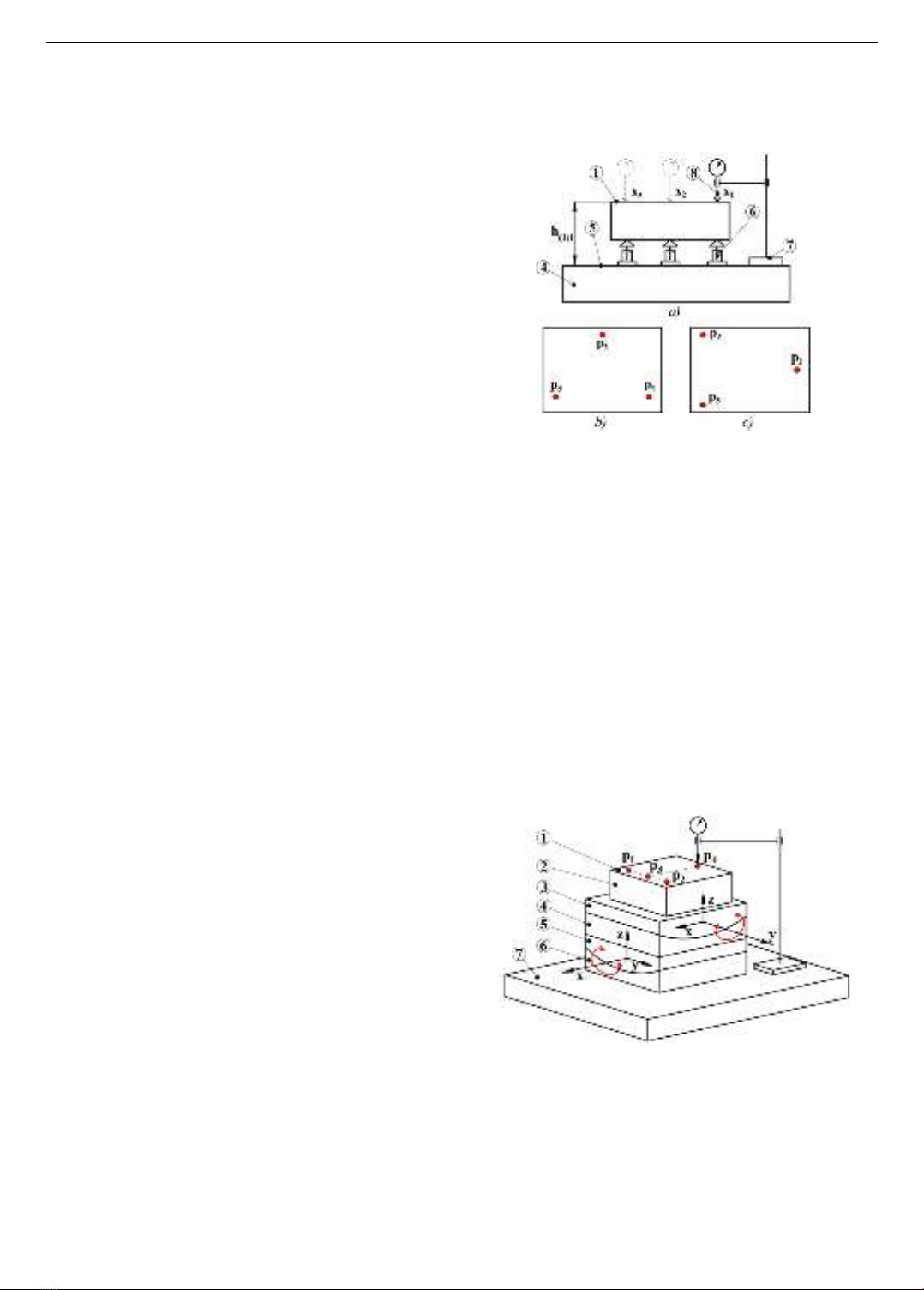
Figure 2 illustrates how to use three levelling screws
to adjust the actual part surface (1) parallel to the surface
plate (5) before measuring the flatness and straightness of
the surface (1). Three red points p1, p2, and p3, which are
located far enough apart on surface (1), are selected, as
shown in two ways in Figs. 2b and 2c. The three levelling
screws are adjusted so that the three values x1, x2, and x3,
obtained from the dial indicator, are equal. At these
points, h11 = h12 = h13 indicates that surface (1) is parallel
to surface (5).
Figure 2. a) Traditional method for adjusting two-plate
parallelism via three-level screws; b) first, 3 points on surfaces
(1) are taken from the top view; c) Second, 3 points on surfaces
(1) are taken from the top view
Another approach to adjust the parallelism between the
actual surface (1) and the surface plate (5) is to use a
mechanism with two trolley-tables that move in
independent arcs around the X and Y axes, as shown in
Figure 3. The center of rotation of the motion tracks should
be symmetrical and perpendicular to the stage surfaces
(3 and 5). The principles of parallelism adjustment in this
approach are as follows: Part (2) is placed on the surface of
the trolley table (3). The dial indicator is used to determine
the altitudes of four points p1, p2, p3, and p4. The values x1
and x2 at points p1 and p2 are used to determine the angle
𝛼𝑥 that trolley-table (3) needs to rotate around the OX axis,
whereas the values y1 and y2 at points p3 and p4 are used to
determine the angle 𝛼𝑦 that trolley-table (5) needs to rotate
around the OY axis.
Figure 3. a) Method for adjusting two-plate parallelism on two
trolley tables around the X- and Y-axes; 1. Actual surface;
2. Part; 3. Trolley table 2; 4. Stage 2; 5. Trolley table 1;
6. Stage 1; 7. Surface plate
The values of the angles 𝛼𝑥 and 𝛼𝑦 are calculated as
follows:
𝛼𝑥= atan[(𝑥1− 𝑥2)/𝑙𝑝1𝑝2] (1)
𝛼𝑦= atan[(𝑦1− 𝑦2)/𝑙𝑝3𝑝4] (2)
32 Tran Minh Sang, Luu Duc Binh, Do Le Hung Toan, Tran Minh Thong, Pham Nguyen Quoc Huy, Vo Nhu Thanh
where 𝑙𝑝1𝑝2 and 𝑙𝑝3𝑝4 are the distances from p1 to p2 and p3
to p4, respectively. Positive values of 𝛼𝑥 and 𝛼𝑦 indicate a
clockwise rotation direction for trolley-table (3) and
trolley-table (5). Conversely, negative values of 𝛼𝑥 and 𝛼𝑦
correspond to counterclockwise rotation directions of the
trolley-table (3) and trolley-table (5), respectively.
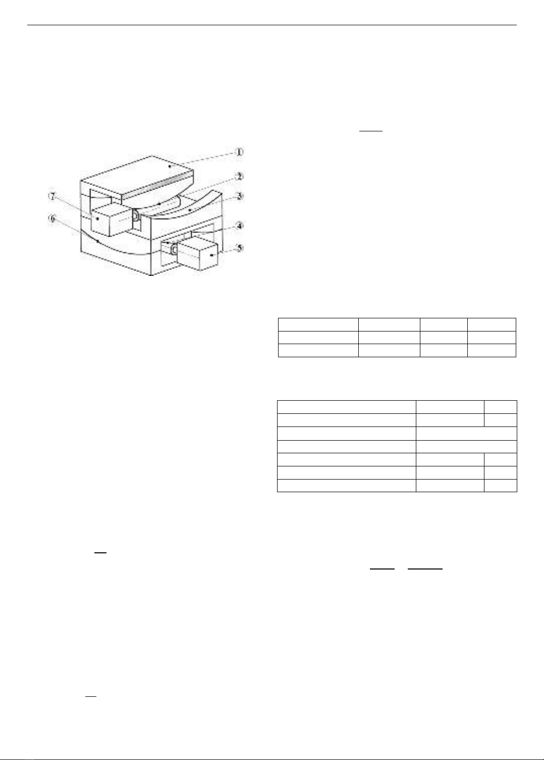
2.2. Selecting the motor capacity and transmission ratio
Figure 4 shows the simplified structure of the designed
device.
Figure 4. Device structure; 1. Actual surface; 2 & 4. Worm-
gear pairs; 3 & 6. Sliding surface 2; 5&7. Stepper motors X, Y
Assume that the device is designed to have a load
capacity of 𝑚𝐿=30kg. The relative motion between the
trolley-tables and the stages is sliding motion with the
sliding friction coefficient taken as 𝑓 = 0.3. Step motor
number 5 is chosen to calculate the capacity. Suppose that
the total mass of two trolley-tables is 𝑚𝑡𝑟 = 2 × 2.4 =
4.8kg, the number of stages is 𝑚𝑠= 1.15 kg, the number
of worm-gear pairs 𝑚𝑤−𝑔 = 0.4kg, the number of stepper
motors is 𝑚𝑠𝑚 = 0.45 kg. We can calculate the total mass
𝑚𝑇 acting on the sliding surface (6) by summing the
masses of the components:
𝑚𝑇= 𝑚𝐿+ 𝑚𝑡𝑟 + 𝑚𝑠+ 𝑚𝑤−𝑔 + 𝑚𝑠𝑚 =36.8kg (3)
The friction force is calculated as follows:
𝐹
𝑚𝑠 = 𝑓. 𝑁 = 0.3 × 9.81 ×36.8 = 108.3 N (4)
The adjustment angle of each trolley-table per second
is chosen as 𝜑𝑡𝑟 = 0.6𝑜. The arc radius of the trolley-tables
is chosen to be 𝑟𝑡𝑟 =200 mm. Therefore, the number of
rotations 𝑛𝑡𝑟, sliding speed 𝑣𝑠 and power 𝑁𝑠 of the trolley-
table are determined via the following formulas:
𝑛𝑡𝑟 = 𝜑 × 60
360 = 0.1 rpm (5)
𝑣𝑠= 𝜑𝑡𝑟 × 𝑟𝑡𝑟 = (0.6𝜋/180) × 0.2 = 0.002 m/s (6)
𝑁𝑠= 𝐹
𝑚𝑠 × 𝑣𝑠=108.3 × 0.002 = 0.217𝑊 (7)
The efficiencies of the worm-gear pair, the bearing pair,
and the coupling are taken as 𝜂𝑤𝑔 = 0.7, 𝜂𝑏 = 0.95, 𝜂𝑐 = 1,
respectively [13, 14]. Thus, the mechanical transmission
system efficiency 𝜂𝑚 is calculated as follows:
𝜂𝑚= 𝜂𝑤𝑔 ×𝜂𝑏× 𝜂𝑐= 0.665 (8)
The power 𝑁𝑠ℎ.𝑚 on the motor out shaft is determined
via the following formula:
𝑁𝑚.𝑠ℎ =𝑁𝑠
𝜂𝑚= 0.326 W (9)
Because of the small angular resolution needed, the
gear ratio of the worm–gear pair is chosen to be 𝑖𝑤𝑔 =500.
The preliminary diameter of the worm wheel is set to
𝑑𝑝𝑤 =500mm and the diameter of the screw shaft is set
to 𝑑𝑝𝑠 =20 mm. The following formula is used to
calculate the output shaft speed of the motor 𝑛𝑚−𝑠ℎand the
torque on the output shaft 𝜏𝑚−𝑠ℎ:
𝑛𝑚.𝑠ℎ = 𝑛𝑡𝑟 × 𝑖𝑤𝑔 =50 rpm (10)
𝜏𝑚.𝑠ℎ = 9.55 ×𝑁𝑚−𝑠ℎ
𝑛𝑚−𝑠ℎ = 0.062 Nm (11)
Based on the requirements for speed and torque on the
output shaft, we choose the stepper motor Nema 17, model
17HS19. This motor features a 48mm long body, a 1.68A
rated current, an integrated planetary gearbox with a gear
ratio 𝑖𝑔𝑏 =13.73, and a maximum allowed torque of 3 Nm
[15]. Thus, the transmission ratio of system 𝑖𝑠 and the
speed of stepper motor 𝑛𝑠𝑝are calculated as follows:
𝑖𝑠= 𝑖𝑤.𝑔 × 𝑖𝑔𝑏 =6865 (12)
𝑛𝑠𝑝 = 𝑛𝑚.𝑠ℎ × 𝑖𝑔𝑏 =686.5 rpm (13)
2.3. Main material and fabrication parameters
The main parts of the device, including all the materials
used in its fabrication process, are detailed in Table 1.
Table 1. Materials used in the fabrication process
Part
Material
Part
Material
Trolley tables
AL 6061
Stages
AL 6061
Worm wheel
POM
Worm
C45
The design parameters for the worm wheel and worm
are listed in Table 2.
Table 2. The main worm wheel and worm parameters
Parameters
Worm wheel
worm
Number of teeth
497
1
Pitch, mm
2.5
Normal module, mm
0.8
Diameter of pitch circle, mm
395,5
18,41
Diameter of head circle, mm
397
20
Diameter of root circle, mm
393,5
16.5
Since the stepper motors have a step angle of 1.80, a
complete 3600 rotation requires 200 steps. The minimum
rotation angles 𝜶𝒙𝒎𝒊𝒏 and 𝜶𝒚𝒎𝒊𝒏of the trolley–tables
around the OX or OY axes, when the motors complete one
step, are calculated as follows:
𝛼𝑥𝑚𝑖𝑛 = 𝛼𝑦𝑚𝑖𝑛 =1.80
𝑖𝑤𝑔
∗.𝑖𝑔𝑏 =1.80
497×13.73 = 0.000260 (14)
where 𝑖𝑤𝑔
∗ is the gear ratio of the actual worm–gear pair
after adjustment.
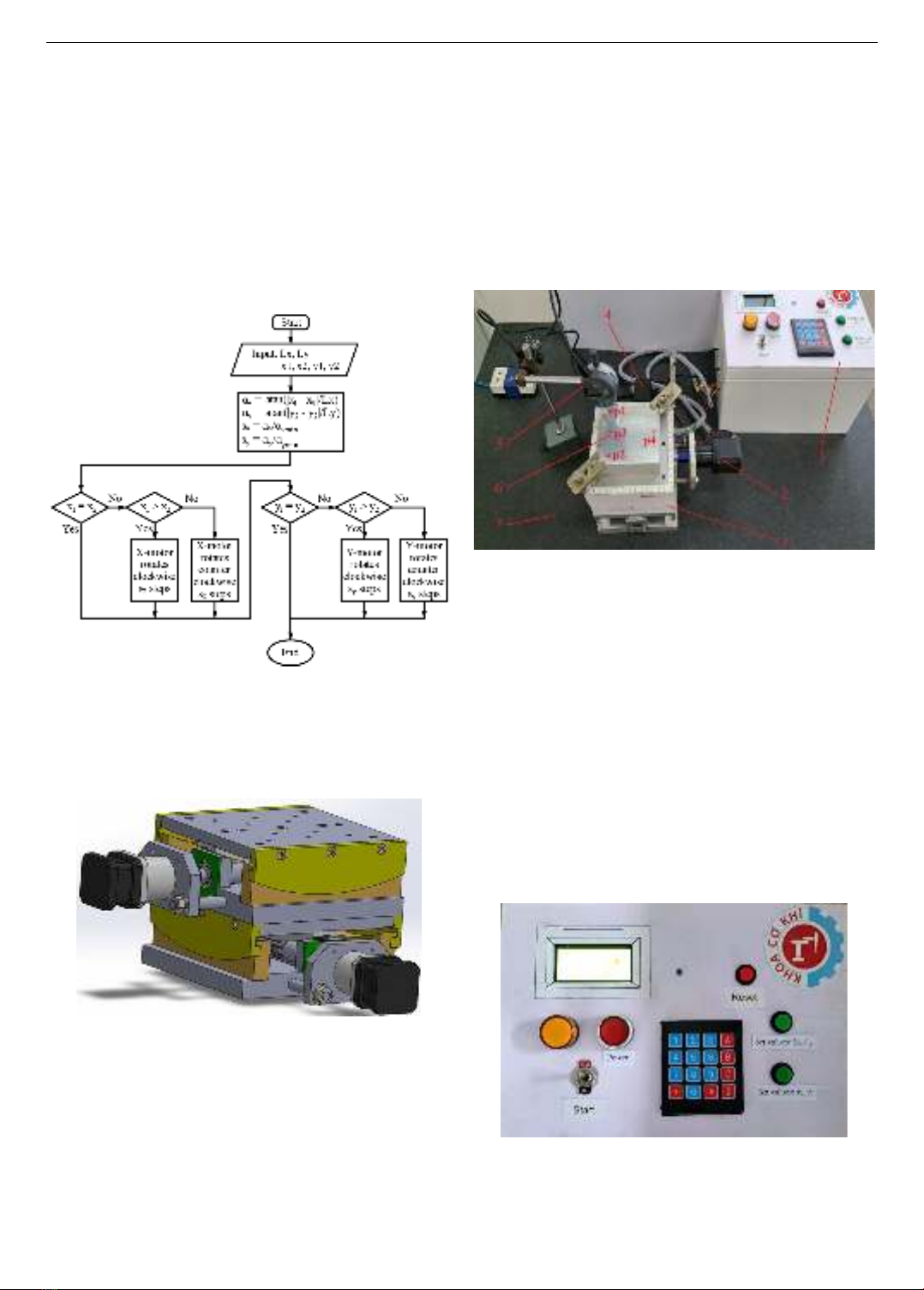
2.4. Device control algorithm
The algorithm used to control the proposed device is
described in Figure 5. Specifically, the device is placed on
the surface plate, and then the measured part is placed on
the device’s worktable. The foundation of the tool holder
is also placed on the surface plate. The digital indicator tip
contacts the adjusted actual surface.
Now, the device turns on. The user then proceeds to
enter the 𝐿𝑥= 𝑝1𝑝2 and 𝐿𝑦= 𝑝3𝑝4 values. The values of
ISSN 1859-1531 - THE UNIVERSITY OF DANANG - JOURNAL OF SCIENCE AND TECHNOLOGY, VOL. 22, NO. 12, 2024 33
x1, x2, y1, and y2 are automatically collected from the digital
indicator at points p1, p2, p3, and p4 (refer to Figure 3). On
the basis of these collected values, the tilt angles 𝛼𝑥 and 𝛼𝑦
are calculated. If x1 is greater than x2, this indicates that
point p1 is higher than point p2. In this case, the X-motor
(motor 5 in Figure 4) rotates clockwise by 𝑠𝑥steps.
Conversely, if x1 is less than x2, the X-motor rotates
counterclockwise by 𝑠𝑥 stpes. If x1 is equal to x2, the
X-motor remains stationary. A similar comparison is
carried out for the y1 and y2 values to determine the
direction of rotation for the Y-motor (motor 7 in Figure 4).
After the angles in X- and Y- axes are adjusted, the
adjustment process is finished.
Figure 5. Flowchart of the device control algorithm
3. Results and discussion
3.1. 3D model and fabricated device
The 3D model of the device is designed via SolidWorks
software, as shown in Figure 6.
Figure 6. 3D model of the device
The device has a worktable area of 150x150 mm and a
total height of 130 mm. The trolley–tables can rotate a
maximum of 300, with 150 in the clockwise and 150 in the
counterclockwise direction.
The device is completely fabricated, assembled, and
connected to the digital indicator and control system, as
shown in Figure 7.
To reduce the time needed to determine the distance
between points p1p2 and p3p4, the working surface is
equipped with four reference segments marked in
millimeters. Similarly, for easy reference to the X and Y
rotation angles of trolley-tables, two reference segments
with angular markings (o) are attached to both sides of the
device. A digital indicator (Mitutoyo 543-791B-10) with
an accuracy of 0.001 mm is connected to the control
system for automatic data acquisition. The accuracy of
the device depends on many factors, one of the most
important being the precision of the mechanical
transmission system. Therefore, careful implementation
during assembly and alignment is necessary to minimize
systematic errors.
Figure 7. Real adjusting system; 1. Device; 2. Y-motor;
3. Control system; 4. X-motor; 5. Digital indicator;
6. Actual surface; 7. Surface plate; p1&p2. X-value points;
p3&p4. Y-value points
Figure 8 shows the interface of the device. The
sequence for using the interface is as follows: press the
“Power” button to supply power to the device; press the
“Start” button to start the adjustment process; the 4x4
matrix keyboard is used to input the 𝐿𝑥and 𝐿𝑦 values; to
confirm the 𝐿𝑥and 𝐿𝑦values, press the “Set values: 𝐿𝑥, 𝐿𝑦”
button after entering 𝐿𝑥and 𝐿𝑦 in turn; next, move the
digital indicator tip to points p1, p2, p3, and p4, press the
“Set values: 𝑥𝑖, 𝑦𝑖" button to confirm the values𝑥1, 𝑥2, 𝑦1
and 𝑦2, respectively; the controller will then calculate the
𝛼𝑥, 𝛼𝑦, 𝑠𝑥, and 𝑠𝑦 values and output the signal to control the
X- and Y-motors; the adjustment process is completed; to
start a new adjustment process, press the “Reset” button.
Figure 8. The device interface
3.2. Device testing
To test the ability to adjust the tilt angle of the designed
device, the xi and yi values are repeated 3 times on the same
34 Tran Minh Sang, Luu Duc Binh, Do Le Hung Toan, Tran Minh Thong, Pham Nguyen Quoc Huy, Vo Nhu Thanh
part that needs to be adjusted, as shown in Figure 7. The
standard length tested is p1p2 = p3p4 = 80 mm. Initially, the
nonparallelism of the actual surfaces to the surface plate is
calculated. These nonparallelism values (∆𝑝𝑟𝑙.𝑥 and ∆𝑝𝑟𝑙.𝑦)
were calculated via Eqn. 15.
∆𝑝𝑟𝑙.𝑥=|𝑥1− 𝑥2|; ∆𝑝𝑟𝑙.𝑦=|𝑦1− 𝑦2| (15)
After the adjustment process, the nonparallelism
between the actual surfaces and the surface plate is
calculated again via Eqn. 15. Finally, the average non-
parallelism values before and after adjusting are compared,
as shown in Table 3.
Table 3. Nonparallelism before the transmission ratio error is
corrected
Exp.
No
Before adjusting
After adjusting
𝒙𝟏
𝒙𝟐
∆𝒑𝒓𝒍.𝒙
𝒙𝟏
𝒙𝟐
∆𝒑𝒓𝒍.𝒙
Direction
X
(mm)
#1
-1.488
-2.066
0.578
-1.760
-1.809
0.049
#2
-1.479
-2.065
0.586
-1.753
-1.803
0.050
#3
-1.467
-2.058
0.594
-1.749
-1.802
0.053
Average
0.586
Average
0.051
Exp.
No
𝒚𝟏
𝒚𝟐
∆𝒑𝒓𝒍.𝒚
𝒚𝟏
𝒚𝟐
∆𝒑𝒓𝒍.𝒚
Direction
Y
(mm)
#1
-2.079
-1.780
0.299
-1.957
-1.920
0.037
#2
-2.078
-1.772
0.306
-1.952
-1.914
0.038
#3
-2.079
-1.769
0.321
-1.947
-1.909
0.038
Average
0.309
Average
0.038
The average nonparallelism values before and after
adjusting are 0.586 and 0.051 in the X direction, and
0.309 and 0.038 in the Y direction, respectively. On the
basic of Eqns. 1 and 2, the required 𝛼𝑥 and 𝛼𝑦 need to be
adjusted by 0.41960 and 0.22130, respectively, to achieve
zero nonparallelism in the X and Y directions.
Additionally, based on Eqns., however, the real adjusted
angles 𝛼𝑥 and 𝛼𝑦 only reach 0.38320 and 0.19410,
respectively, resulting in differences of 8.67% and
12.29% compared with the required angles. Errors in the
system transmission ratio and assembly errors cause this
difference. To compensate, offset rotation angles of
8.67% and 12.29% are added in the X and Y directions
during adjustment. Following error compensation, the
device was retested, and the results presented in Table 4
demonstrate significant improvement.
Table 4. Nonparallelism after the transmission ratio error is
corrected
Exp.
No
Before adjusting
After adjusting
𝒙𝟏
𝒙𝟐
∆𝒑𝒓𝒍.𝒙
𝒙𝟏
𝒙𝟐
∆𝒑𝒓𝒍.𝒙
Direction
X
(mm)
#1
-1.471
-2.062
0.591
-1.781
-1.780
0.001
#2
-1.467
-2.055
0.588
-1.780
-1.780
0.000
#3
-1.470
-2.063
0.593
-1.785
-1.783
0.002
Average
0.591
Average
0.001
Exp.
No
𝒚𝟏
𝒚𝟐
∆𝒑𝒓𝒍.𝒚
𝒚𝟏
𝒚𝟐
∆𝒑𝒓𝒍.𝒚
Direction
Y
(mm)
#1
-2.075
-1.768
0.307
-1.930
-1.930
0.000
#2
-2.075
-1.764
0.311
-1.926
-1.928
0.002
#3
-2.072
-1.759
0.313
-1.922
-1.921
0.001
Average
0.310
Average
0.001
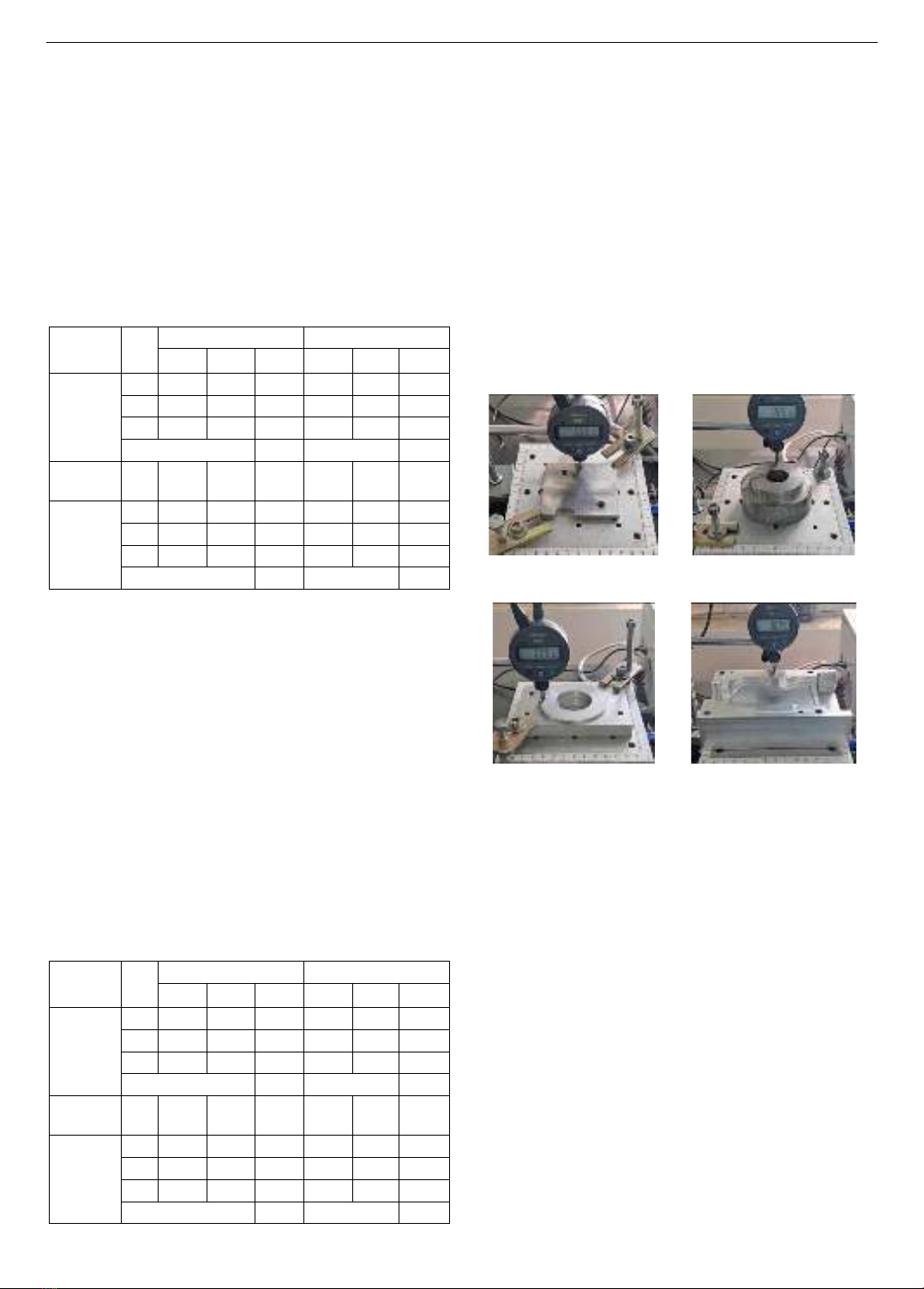
Table 4 shows an average nonparallelism of 0.001
between the actual surface and the surface plate when
adjusted by the proposed system. The device is used to
make adjustments on various other machine elements, as
shown in Figure 9. The results obtained still show an
average nonparallelism within 0.001 mm.
The nonparallelism error is in the range of 0.001
because of the highly sensitive contact measuring tip of the
digital indicator, which can be easily affected by dust in the
measuring environment. The experimental results
demonstrate the proposed device's effectiveness in
mechanical measurement applications. However, like any
measurement device, the proposed device needs to be
periodically calibrated based on the frequency of use to
minimize the impact of environmental variables and
mechanical wear on data reliability. Currently, the device
is checked for accuracy every two weeks.
a) Part 1: 𝐿𝑥=60𝑚𝑚 and
𝐿𝑦=70𝑚𝑚
b) Part 2:
𝐿𝑥= 𝐿𝑦=50𝑚𝑚
c) Part 3:
𝐿𝑥= 𝐿𝑦=70𝑚𝑚
d) Part 4: 𝐿𝑥=100𝑚𝑚 and
𝐿𝑦=130𝑚𝑚
Figure 9. Adjust the parallelism between the measured surface
and the surface plate of some machine elements
Although CMM machines offer high accuracy and
many accompanying features, their cost presents a
significant barrier for small-scale companies. Currently,
the average price of a CMM machine in the Vietnamese
market is over 40,000 USD. The proposed device offers
an alternative solution, with a manufacturing cost of
under 1,000 USD. Furthermore, in small and medium-
sized mechanical workshops, adjusting the measured
surface parallel to the surface plate using three leveling
screws is both time-consuming and requires skilled
technicians. The proposed device significantly reduces
adjustment time by 4 to 5 times and minimizes
dependence on the technician's skills.
4. Conclusions
This study designed and manufactured a tilt angle
adjustment device to make the measured actual surface
parallel to a surface plate. The device features two
independent stages, each responsible for adjusting the


![Túi khí an toàn (airbag): Những điều nên biết [Cập nhật 2024]](https://cdn.tailieu.vn/images/document/thumbnail/2011/20111122/gauhaman123/135x160/oto_co_ban_44__0147.jpg)


![Giáo trình Cấu trúc dữ liệu và giải thuật - Trường CĐ Cơ điện Hà Nội [Mới nhất]](https://cdn.tailieu.vn/images/document/thumbnail/2026/20260323/lionelmessi01/135x160/58171774381670.jpg)


![Giáo trình Tiện nâng cao (Nghề Cắt gọt kim loại, Trình độ Cao đẳng) - Trường Cao đẳng Cơ điện Hà Nội [Mới nhất]](https://cdn.tailieu.vn/images/document/thumbnail/2026/20260323/lionelmessi01/135x160/48101774403543.jpg)


