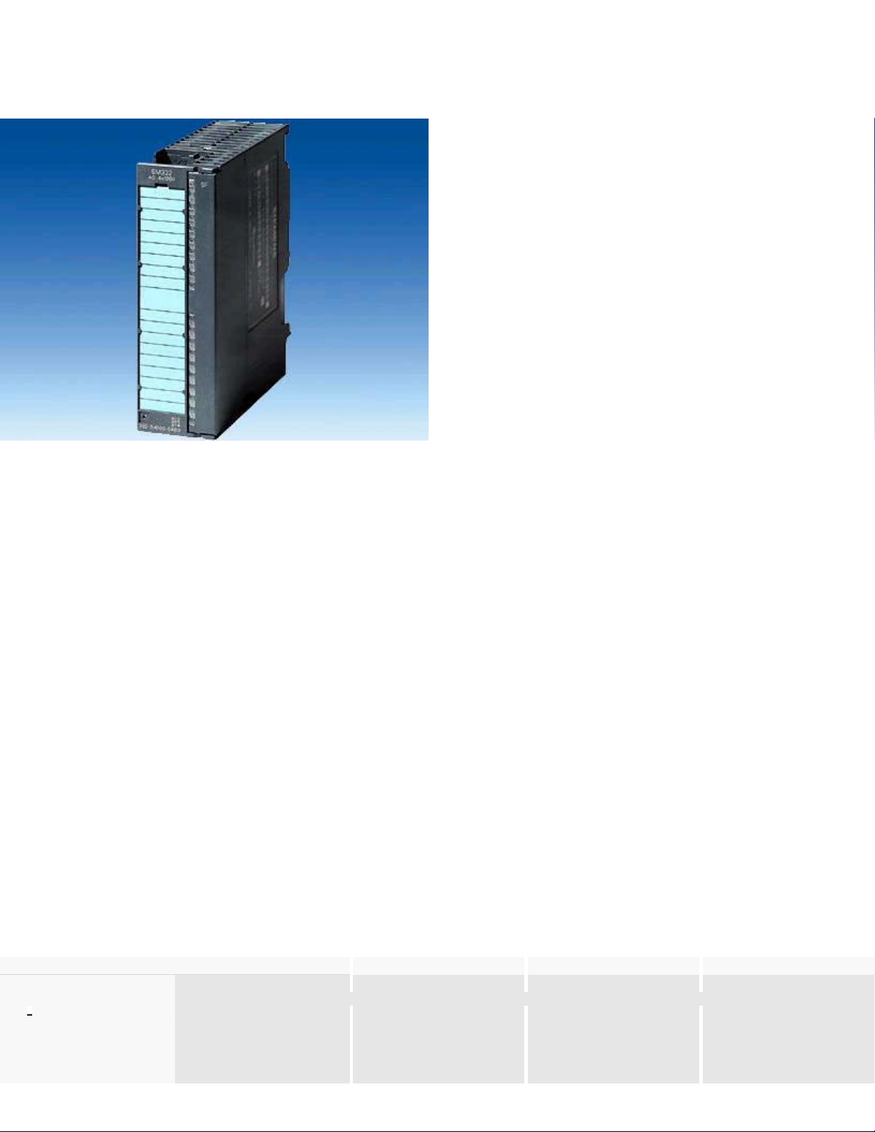
Analog Modules - SM 332 analog output
Overview
zAnalog outputs
zFor the connection of analog actuators
Application
A
nalog output modules can be used to output analog signals from the PLC to the process. They are suitable for connecting analog actuators.
Function
The analog output modules convert digital signals from the PLC into analog signals for the process.
The modules feature the following:
zResolution from 12 to 15 bit
zVarious voltage and current ranges:
The ranges are set independently for each channel using parameterization software.
zInterrupt capability:
The module transmits diagnostic alarm messages to the controller’s CPU in the event of errors.
zDiagnostics:
The module sends detailed diagnostic information to the CPU.
Technical specifications
6ES7 332-5HB01-0AB0 6ES7 332-5HD01-0AB0 6ES7 332-5HF00-0AB0 6ES7 332-7ND02-0AB0
Voltages and currents
Load voltage L+
Rated value (DC) 24 V 24 V 24 V 24 V
Current consumption
zfrom load voltage L+ (no load),
max.
135 mA 240 mA 340 mA 290 mA
zfrom backplane bus 5 V DC, 60 mA 60 mA 100 mA 120 mA
Analo
g
Modules - SM 332 analo
g
out
p
ut CA 01
Seite 1 von 3

max.
zPower dissipation, typical 3 W 3 W 6 W 3 W
Connection system
zRequisite front connector 20-pin 20-pin 40-pin 20-pin
Analog outputs
zNumber of analog outputs 2 4 8 4; clock synchronous operation
zLength of cable shielded, max 200 m 200 m 200 m 200 m
zVoltage output, short-circuit
protection
Yes Yes Yes Yes
zVoltage output, short-circuit
current, max
25 mA 25 mA 25 mA 40 mA
zCurrent output, open-circuit
voltage, max.
18 V 18 V 18 V 18 V
Output ranges, voltage
0 to 10 V Yes Yes Yes Yes
1 to 5 V Yes Yes Yes Yes
-10 to +10 V Yes Yes Yes Yes
Output ranges, current
0 to 20 mA Yes Yes Yes Yes
-20 to +20 mA Yes Yes Yes Yes
4 to 20 mA Yes Yes Yes Yes
Burden resistance (in the nominal
output range)
at voltage outputs, min. 1 kΩ 1 kΩ 1 kΩ 1 kΩ
at voltage outputs,
capacitive load, max.
1 µF 1 µF 1 µF 1 µF
at current outputs, max. 500 Ω 500 Ω 500 Ω 500 Ω
at current outputs, inductive
load, max.
10 mH 10 mH 10 mH 1 mH
Analog value formation
Integration and conversion
time/triggering per channel
with over-range (bits incl.
sign), max
12 Bit; +/- 10 V, +/- 20mA, 4 to 20
mA, 1 to 5 V: 11 bits + sign, 0 to 10 V,
0 to 20 mA: 12 bits
12 Bit; +/- 10 V, +/- 20mA, 4 to 20
mA, 1 to 5 V: 11 bits + sign, 0 to 10
V, 0 to 20 mA: 12 bits
12 Bit; +/- 10 V, +/- 20mA, 4 to 20
mA, 1 to 5 V: 11 bits + sign, 0 to 10
V, 0 to 20 mA: 12 bits
16 Bit
Conversion time (per
channel)
0.8 ms 0.8 ms 0.8 ms 200 µs; in clocked mode 640µs
Settling time
for resistive load 0.2 ms 0.2 ms 0.2 ms 0.2 ms
for capacitive load 3.3 ms 3.3 ms 3.3 ms 3.3 ms
for inductive load 0.5 ms; 0.5 ms(1mH); 3.3ms(10mH) 0.5 ms; 0.5ms (1mH); 3.3ms (10mH) 0.5 ms; 0.5ms (1mH); 3.3ms (10mH) 0.5 ms
Error/accuracies
Operational limit in the entire
temperature range
Relative to the output range,
voltage
+/- 0,5 % +/- 0,5 % +/- 0,5 % +/- 0,12 %
Relative to the output range,
current
+/- 0,6 % +/- 0,6 % +/- 0,6 % +/- 0,18 %
Basic error limit (operational limit at
25 °C)
relative to the output range,
voltage
+/- 0,4 % +/- 0,4 % +/- 0,4 % +/- 0,02 %
relative to the output range,
current
+/- 0,5 % +/- 0,5 % +/- 0,5 % +/- 0,02 %
Status information/ interrupts/
diagnostics
zApplying substitute values Yes; parameterizable Yes; parameterizable Yes; parameterizable Yes; parameterizable
Interrupts
Diagnostic interrupt Yes; parameterizable Yes; parameterizable Yes; parameterizable Yes
Diagnostics
Diagnostic information can
be read out
Yes Yes Yes
Insulation
zInsulation tested with 500 V DC 500 V DC 500 V DC 1500 V DC
Potentials/ electrical isolation
Analog output functions
between the channels and
the backplane bus
Yes Yes Yes Yes
Dimensions and weight
zWeight, approx. 220 g 220 g 272 g 220 g
zWidth 40 mm 40 mm 40 mm 40 mm
zHeight 125 mm 125 mm 125 mm 125 mm
zDepth 120 mm 120 mm 120 mm 120 mm
Analo
g
Modules - SM 332 analo
g
out
p
ut CA 01
Seite 2 von 3

Analo
g
Modules - SM 332 analo
g
out
p
ut CA 01
Seite 3 von 3
![Tập bài giảng Xử lý tín hiệu số [chuẩn nhất]](https://cdn.tailieu.vn/images/document/thumbnail/2021/20211119/cucngoainhan3/135x160/1203186432.jpg)


![Câu hỏi trắc nghiệm Lập trình C [mới nhất]](https://cdn.tailieu.vn/images/document/thumbnail/2025/20251012/quangle7706@gmail.com/135x160/91191760326106.jpg)