
* Corresponding author.
E-mail addresses: pawanar@rediffmail.com (P.K. Arora)
© 2017 Growing Science Ltd. All rights reserved.
doi: 10.5267/j.esm.2017.5.001
Engineering Solid Mechanics (2017) 185-198
Contents lists available at GrowingScience
Engineering Solid Mechanics
homepage: www.GrowingScience.com/esm
Determination of crack growth direction for multiple offset edge cracks of a finite
plate
P.K. Aroraa*, S C. Srivastavab and Harish Kumarc
aGalgotias College of Engineering and Technology, Greater Noida, India
bBirla Institute of Technology Mersa, Ranchi, India
cCSIR – National Physical Laboratory, New Delhi, India
A R T I C L EI N F O A B S T R A C T
Article history:
Received 6 January, 2017
Accepted 20 May 2017
Available online
21 May 2017
An approximated crack growth direction and coalescence of the multiple cracks were obtained
for an aluminum alloy plate by the finite element approach (FEA). Self-similar as well as non-
self-similar crack growths were observed based on relative position of multiple cracks. The FE
predictions of crack growth direction are validated with an experimental results and good
agreement is established. Typical numerical results are presented to examine the effect of
changing the crack tip distance (S), crack offset distance (H) on crack growth direction and
coalescence of a finite aluminum alloy aluminum plate. Based on the analysis and experimental
results, a new mathematical models for self-similar and non-self similar crack growth are
introduced.
© 2017 Growing Science Ltd. All rights reserved.
Keywords:
Crack initiation angle
Coalescence
Offset-crack
Self-similar crack growth
Non self-similar crack growth
Nomenclature
a crack length
w width of Plate
h height of plate
θ crack initiation angle
t thickness of plate
α crack inclination angle
F applied load
μ Poisson’s ratio
S crack tip distance
H crack offset distance
E modulus of elasticity
KI & KII stress intensity factor for Mode-I &
Mode-II
E modulus of elasticity
σy yield stress
σu ultimate stress
δ elongation
εf failure strain
εep effective plastic strain

186
1. Introduction
Aluminum (Al) alloy structures have found extensive applications in aerospace, defense, transport
industry, utensil industries, etc. due to unique properties such as high strength to weight ratio, fatigue
strength, corrosion resistance, and, ductility with high structural efficiency, durability, and workability.
In comparison with fiber reinforced composite and other alloys, Al alloy offers more cost saving with
greater performance increments due to low density. However, the use of Al alloy has been inhibited in
their potential applications due to limited ductility, inferior low cycle fatigue resistance, and low
fracture toughness.
The crack interaction involves two typical features of crack growth behaviors: crack coalescence
and stagnation. The coalescence of approaching cracks, is frequently observed in crack growth
processes. On the other hand, cracks may stop growing due to the stress shielding effect caused by the
presence of other cracks in the neighborhood. The interaction between the multiple cracks can be
studied either analytically or experimentally. Analytical approach involves numerical evaluations based
on empirical relationships between the crack growth rate and the stress intensity factors (SIFs). The
relative position of interacting crack changes according to their growth. Therefore, it is necessary to
examine not only the relationship between the SIFs value and the relative position, but also the change
in this relationship with the crack growth process needs to study.
Multiple cracks of an aircraft structure and rivet holes can be initiated because of cyclic load and
engine vibration during flight. The presence of crack may reduce strength and stability of an aircraft
and its components considerably. The proposed concept of crack growth is useful while assessing
damage tolerance behavior and component life of an aircraft. It can further be used during
implementation of repair schemes for the cracks observed during service phase of aircraft structural
components.
The interaction between multiple cracks has a major influence on crack growth behaviors. This
influences particularly significant in stress corrosion cracking (Kamaya, & Totsuka, 2002), welding
(Cisilino & Aliabadi, 1997; Wessel et al., 2001), multiple site damage in aging aircraft (Zhao et al. 2012)
and cold expended fasteners holes in aircraft components (Lacarac et al., 2004). The growth direction
is computed either by using strain energy density (SED) criterion or maximum tangential stress (MTS)
criterion (Sih, 1974; Sih & Barthelemy, 1980; Yan, 2006, Aliha et al., 2016a,b; Akbardoost et al., 2014;
Mirsayar et al., 2016, Ayatollahi et al., 2006,2011; Aliha & Ayatollahi 2008) as no such standard
relations is available to compute the crack growth direction based on the relative crack positions. Strain
energy release rate based on virtual crack closure technique is developed by introducing an interface
element to solve crack growth problem (Xie et al., 2006; Liu et al., 2011). Experimental and finite
element studies on mode-I and mode –II crack growth shows good agreement (Maiti & Mahanty, 1990;
Lee & Jeon, 2011). Crack propagation is perhaps the most thoroughly study need to carry out in the
area of fracture mechanics. However, the theories that have so far been developed are not fully capable
of predicting the crack growth process that occurs in service. The problem can be further complicated
by multiple cracks in the structure. The magnitude of the interaction is dependent on various factors,
such as, relative size, relative locations, crack shape, and number of cracks (Kamaya, 2008).
The SIFs are very important parameters for fracture mechanics analyses. An essential part of the
solution of fracture problem is the evaluation of the SIFs. In most of the studies under multiple crack
systems, SIFs are either evaluated from the superposing and compounding the stress intensity factors
solution (Bombardier & Liao, 2011), finite element model and force method (De Morais, 2007) and
energy release-rate method (Wang & Zhang, 1999). The effects of uncertainties in material properties,
crack length, and load on SIFs were explored using Taylor stochastic finite element method (SFEM)
(Xiaofeng et al., 2009) and Gaussian Monte Carlo method (Romlay et al., 2010; Cadini et al., 2009).
The available literature is unable to detect the effect of relative crack positions on multiple crack

P.K. Arora et al. / Engineering Solid Mechanics 5 (2017)
187
configurations. The present study focuses on the influence of crack position defined by crack offset
distance, and crack tip distance on growth direction.
2. Material and specimen
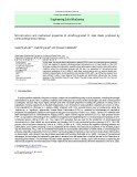
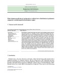
The study of crack growth direction under tensile loading was conducted considering multiple
offset and inclined cracks. Crack growth direction is determined considering multiple edge cracks
(Fig.1a), multiple central cracks (Fig.1b), and multiple inclined central crack (Fig. 1c). An Al alloy
plate of 60x200x1 mm3 was used as a specimen for all the cases.
Fig. 1. Specimen geometry along with multiple cracks
Two holes of diameter 2 mm were created by drilling at the center of cracks and edge cracks were
generated on specimen by the water jet machine (WJM). All inclined cracks were introduced at an
angle 60o relative to the vertical axis. Mechanical properties of an Al alloy used in the computation as
shown in Table 1.
Table 1. Mechanical Property of tested Al alloy
Specimen configuration E (GPa) μ σ
y
(MPa) σu (MPa) %δ ε
f
7072-Aluminum alloy 70 0.3 99 106 14-15 0.25-0.30
w
1
2a
2
2a
h
S
H
(a) Offset edge crack
(
b
)
Offset central crack
h
w
(c) central inclined crack
w
H h
F F

188
3. Methodology
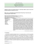
Fig. 2 presents the systematic overview of integrated approach used in present study for the multiple
crack configurations, which deals with simulation of crack propogation by testing and FE approach.
Testing of the specimen is carried out using universal testing machine (UTM), whereas FE analysis is
carried out using explicit code of LS Dyna software. Effect of changing the crack tip distance and
crack offset distance on crack growth direction is studied using maximum nominal strain criterion
discuseed in susequent section 3.1.2. Crack growth angle is measured on fratured specimen during
experiment and FE simulation.Details of the experiment and FE anaysis are presented in susequent
section 3.4.
3.1 Damage initiation
Present study discusses the crack growth and coalesence of multiple cracks by the cohesive damage
approach (Li & Chandra 2003). Damage initiation refers to the beginning of degradation of the response
of a material point. The process of degradation starts when the stresses and/or strains satisfy certain
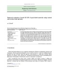
damage initiation criteria. Fig. 3 shows a typical traction-separation response with a failure mechanism.
Several damage initiation criteria are available and are discussed below. A value of 1 or higher indicates
that the initiation criterion has been met.
Fig. 2. Systematic overview of present study
traction
000
(,)
nst
δ0 δf
Separation
Fig. 3. Typical traction-separation response
Integrated approach
Loading and clamping of
specimen on UTM
Monitoring of crack growth
Fracture of specimen
Preparation of specimen for
different cracks configurations
Results interpretation
Generation of polynomial
equation for crack growth
Surface model for different multiple
cracks configurations
Defining the material properties for
crack and non crack zone
Mesh generation and defining the
Specimen properties
Application of loads and boundary
conditions
Defining the simulation time
Analysis using explicit code

P.K. Arora et al. / Engineering Solid Mechanics 5 (2017)
189
3.1.1 Maximum Nominal Stress Criterion
Damage is assumed to initiate when the maximum nominal stress ratio reaches a value of one. This
criterion can be represented as
1,,max
o
t
t
o
s
s
o
n
n
(1)
3.1.2 Maximum Nominal Strain Criterion
Damage is assumed to initiate when the maximum nominal strain ratio reaches a value of one. This
criterion can be represented as (Erdogan & Sih, 193)
1,,max
o
t
t
o
s
s
o
n
n
(2)
The crack starts propogaating through mesh once the effective palstic strain more then or equal to
the failure starin of the material
fep
(3)
3.1.3 Quadratic Nominal Stress Criterion
Damage is assumed to initiate when a quadratic interaction function involving the nominal stress
ratios reaches a value of one. This criterion can be represented as
1
222
o
t
t
o
s
s
o
n
n
.
(4)
3.1.4 Quadratic Nominal Strain Criterion
Damage is to be initiated when a quadratic interaction function involving the nominal strain
ratios reaches a value of one. This criterion can be represented as
1
222
o
t
t
o
s
s
o
n
n
,
(5)
where ,, o
s
o
n
and o
t
represent the peak values of the nominal stress when the deformation is either
purely normal to the interface or purely in the first or the second shear direction, respectively. In the
same manner ,, o
s
o
n
and o
t
represent the peak values of the nominal strain when the deformation is
either purely normal to the interface or in the first or the second shear direction respectively.
3.2 Damage Evolution
The damage evolution law describes the rate at which the material stiffness is degraded once the
corresponding initiation criterion is reached. A scalar damage variable, D, shows the overall damage
in the material and captures the combined effects of all the active mechanisms. Initially it has a value
of zero. If damage evolution is modeled, D monotonically evolves from 0 to 1 upon further loading


![Đề cương ôn thi Nguyên lý máy [mới nhất]](https://cdn.tailieu.vn/images/document/thumbnail/2025/20251231/cuchoami2510/135x160/90481767694770.jpg)
