13
Synchronous Digital Hierarchy
(SDH) and Synchronous
Optical Network (SONET) zyxwvutsrqponmlkjihgfedcbaZYXWVUTSRQPONMLKJIHGFEDCBA
The synchronous digital hierarchy (SDH) is emerging as the universal technology for
transmission in telecommunications networks. Since the first publication
of
international
standards by ITU-T in
1989,
SDH equipment has been rapidly developed and deployed across the
world, and is rapidly taking over from its predecessor, the Plesiochronous Digital Hierarchy
(PDH). This chapter describes SDH and the North American equivalent of SDH, SONET
(Synchronous Optical Network), from which it grew. In particular, the chapter describes the
features of SDH which characterize its advantages over PDH. zyxwvutsrqponmlkjihgfedcbaZYXWVUTSRQPONMLKJIHGFEDCBA
13.1
HISTORY
OF
THE SYNCHRONOUS DIGITAL
HIERARCHY (SDH)
The zyxwvutsrqponmlkjihgfedcbaZYXWVUTSRQPONMLKJIHGFEDCBA
synchronous digital hierarchy
(SDH)
was developed from its North American
forerunner
SONET
(synchronous optical network).
SDH is the most modern type of
transmission technology, and as its name suggests it is based on a synchronous multi-
plexing technology. The fact that SDH is synchronous adds greatly to the efficiency
of
the transmission network, and makes the network much easier to manage.
13.2 THE PROBLEMS
OF
PDH TRANSMISSION
Historically, digital telephone networks, modern data networks and the transmission
infrastructures serving them have been based
on
a technology called
PDH
(Plesio-
chronous Digital Hierarchy)
as we discussed in Chapter 5. As we also discussed, three
distinct PDH hierarchies evolved, as we summarize in Figure
13.1.
They share three
common attributes.
267
Networks and Telecommunications: Design and Operation, Second Edition.
Martin P. Clark
Copyright © 1991, 1997 John Wiley & Sons Ltd
ISBNs: 0-471-97346-7 (Hardback); 0-470-84158-3 (Electronic)
268 zyxwvutsrqponmlkjihgfedcbaZYXWVUTSRQPONMLKJIHGFEDCBASYNCHRONOUS DIGITAL HIERARCHY AND SYNCHRONOUS OPTICAL NETWORK zyxwvutsrqponmlkjihgfedcbaZYXWVUTSRQPONMLKJIHGFEDCBA
(a)
Europe
64 2048 a448 34 368 139 264 564 992
kbit/s
(El zyxwvutsrqponmlkjihgfedcbaZYXWVUTSRQPONMLKJIHGFEDCBA
1
(E21 (E31
=
X4
X4
=
X4
-
X4
-
X32
-
MUX
-
MUX
-
MUX
-
MUX
-
MUX zyxwvutsrqponmlkjihgfedcbaZYXWVUTSRQPONMLKJIHGFEDCBA
b
L
hierarchy level zyxwvutsrqponmlkjihgfedcbaZYXWVUTSRQPONMLKJIHGFEDCBA
0
1
2
3
4
5
(b)
North
America
64 1544 6312 44 736 274 176
kbiffs
(DSO) (DS1
or
T1) (DS2
or
T2) (DS3
or
T3)
.
.
1
-
3x241 3x4
I
4x7 HX6
I
,
MUX MUX MUX MUX
U
U
U U
hierarchy level
0
1
2
3
4
(c)
Japan
64 1544 631 2 32 064 97 728
kbiffs
X 24 X4 X5 X3
MUX MUX MUX MUX zyxwvutsrqponmlkjihgfedcbaZYXWVUTSRQPONMLKJIHGFEDCBA
b
hierarchy level
0
1
2
3
4
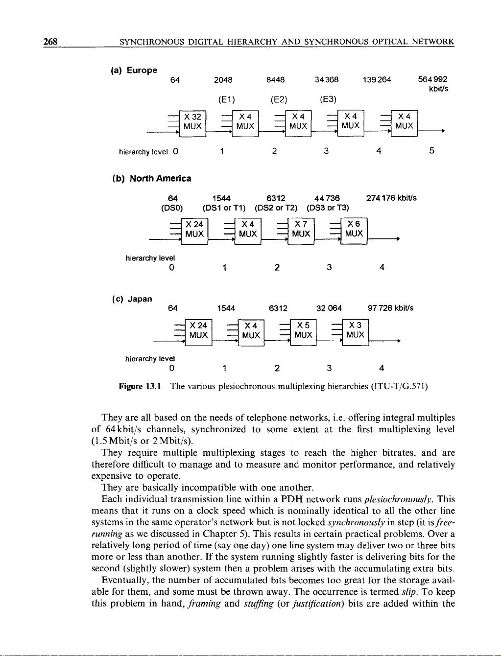
Figure
13.1
The various plesiochronous multiplexing hierarchies
(ITU-T/G.571)
They are all based on the needs of telephone networks, i.e. offering integral multiples
of
64
kbit/s channels, synchronized to some extent at the first multiplexing level
(1.5
Mbit/s or
2
Mbit/s).
They require multiple multiplexing stages to reach the higher bitrates, and are
therefore difficult to manage and to measure and monitor performance, and relatively
expensive to operate.
They are basically incompatible with one another.
Each individual transmission line within a
PDH
network runs zyxwvutsrqponmlkjihgfedcbaZYXWVUTSRQPONMLKJIHGFEDCBA
plesiochronously.
This
means that it runs on a clock speed which is nominally identical to all the other line
systems in the same operator’s network but is not locked
synchronously
in step (it is
free-
running
as we discussed in Chapter
5).
This results in certain practical problems. Over a
relatively long period of time (say one day) one line system may deliver two or three bits
more or less than another. If the system running slightly faster is delivering bits for the
second (slightly slower) system then a problem arises with the accumulating extra bits.
Eventually, the number of accumulated bits becomes too great for the storage avail-
able for them, and some must be thrown away. The occurrence is termed
slip.
To keep
this problem in hand,
framing
and
stufJing
(or
justlJication)
bits are added within the
THE PROBLEMS
OF
PDH TRANSMISSION zyxwvutsrqponmlkjihgfedcbaZYXWVUTSRQPONMLKJIHGFEDCBA
269
normal multiplexing process, and are used to compensate. These bits help the two end
systems to communicate with one another, speeding up or slowing down as necessary
to keep better in step with one another. The extra framing bits account for the differ-
ence, for example, between 4 zyxwvutsrqponmlkjihgfedcbaZYXWVUTSRQPONMLKJIHGFEDCBA
X
2048(E1 bitrate)
=
8192 kbit/s and the actual E2 bitrate
(8448 kbit/s, see Figure 13.1).
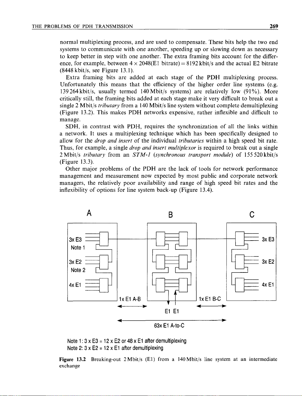
Extra framing bits are added at each stage of the PDH multiplexing process.
Unfortunately this means that the efficiency of the higher order line systems (e.g.
139264 kbit/s, usually termed 140Mbit/s systems) are relatively low (91%). More
critically still, the framing bits added at each stage make it very difficult to break out a
single 2 Mbit/s zyxwvutsrqponmlkjihgfedcbaZYXWVUTSRQPONMLKJIHGFEDCBA
tributary
from a 140 Mbit/s line system without complete demultiplexing
(Figure 13.2). This makes PDH networks expensive, rather inflexible and difficult to
manage.
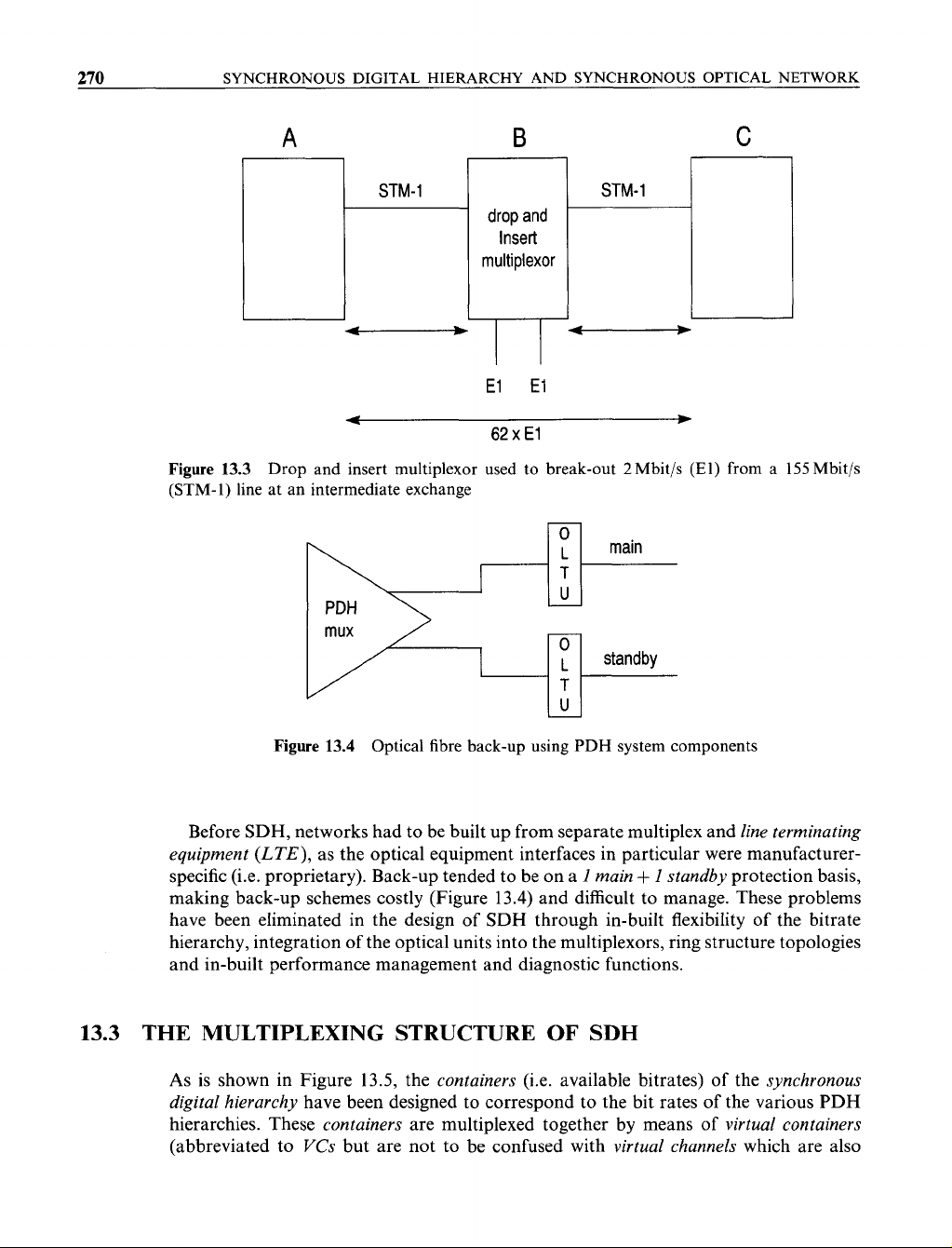
SDH, in contrast with PDH, requires the synchronization of all the links within
a network. It uses a multiplexing technique which has been specifically designed to
allow for the
drop and insert
of
the individual
tributaries
within a high speed bit rate.
Thus, for example, a single
drop and insert multiplexor
is required to break out a single
2 Mbit/s
tributary
from an zyxwvutsrqponmlkjihgfedcbaZYXWVUTSRQPONMLKJIHGFEDCBA
STM-I
(synchronous transport module)
of
155
520
kbit/s
(Figure 13.3).
Other major problems of the PDH are the lack of tools for network performance
management and measurement
now
expected by most public and corporate network
managers, the relatively poor availability and range of high speed bit rates and the
inflexibility
of
options for line system back-up (Figure 13.4). zyxwvutsrqponmlkjihgfedcbaZYXWVUTSRQPONMLKJIHGFEDCBA
A
B zyxwvutsrqponmlkjihgfedcbaZYXWVUTSRQPONMLKJIHGFEDCBA
C
3xE3
Note
1
=2
3x E2
Note
2
4xEl
IX
El
B-C
t--------)
-
El El
t
W
63~ El
A-to-C
Note
1
:
3
X
E3
=
12
X
E2
or
48
X
El
after demultiplexing
Note
2: 3
X
E2
=
12
X
El
after demultiplexing zyxwvutsrqponmlkjihgfedcbaZYXWVUTSRQPONMLKJIHGFEDCBA
a=
3x E3
3x E2
4xEl zyxwvutsrqponmlkjihgfedcbaZYXWVUTSRQPONMLKJIHGFEDCBA
Figure
13.2
Breaking-out 2Mbit/s
(El)
from a 140Mbit/s line system at an intermediate
exchange
270 zyxwvutsrqponmlkjihgfedcbaZYXWVUTSRQPONMLKJIHGFEDCBA
SYNCHRONOUS DIGITAL HIERARCHY AND SYNCHRONOUS OPTICAL NETWORK
A zyxwvutsrqponmlkjihgfedcbaZYXWVUTSRQPONMLKJIHGFEDCBA
B zyxwvutsrqponmlkjihgfedcbaZYXWVUTSRQPONMLKJIHGFEDCBA
C
STM-l
STM-1
drop and
Insert
multiplexor
-
-
El
El
62
X
El zyxwvutsrqponmlkjihgfedcbaZYXWVUTSRQPONMLKJIHGFEDCBA
Figure
13.3
Drop and insert multiplexor used to break-out
2
Mbit/s
(El)
from a
155
Mbit/s
(STM-1) line at an intermediate exchange zyxwvutsrqponmlkjihgfedcbaZYXWVUTSRQPONMLKJIHGFEDCBA
m
standby
Figure
13.4 Optical fibre back-up using PDH system components
Before
SDH,
networks had to be built up from separate multiplex and zyxwvutsrqponmlkjihgfedcbaZYXWVUTSRQPONMLKJIHGFEDCBA
line terminating
equipment
(LTE),
as the optical equipment interfaces in particular were manufacturer-
specific (i.e. proprietary). Back-up tended to be on a
I
main
+
I
standby
protection basis,
making back-up schemes costly (Figure
13.4)
and difficult to manage. These problems
have been eliminated in the design of
SDH
through in-built flexibility of the bitrate
hierarchy, integration of the optical units into the multiplexors, ring structure topologies
and in-built performance management and diagnostic functions.
13.3
THE MULTIPLEXING STRUCTURE
OF
SDH
As
is shown in Figure
13.5,
the
containers
(i.e. available bitrates)
of
the
synchronous
digital hierarchy
have been designed to correspond
to
the bit rates of the various
PDH
hierarchies. These
containers
are multiplexed together by means of
virtual containers
(abbreviated to VCs but are not to be confused with
virtual channels
which are also
THE MULTIPLEXING STRUCTURE
OF
SDH zyxwvutsrqponmlkjihgfedcbaZYXWVUTSRQPONMLKJIHGFEDCBA
271 zyxwvutsrqponmlkjihgfedcbaZYXWVUTSRQPONMLKJIHGFEDCBA
XN
X1 zyxwvutsrqponmlkjihgfedcbaZYXWVUTSRQPONMLKJIHGFEDCBA
pointer processing zyxwvutsrqponmlkjihgfedcbaZYXWVUTSRQPONMLKJIHGFEDCBA
c-
multiplexing
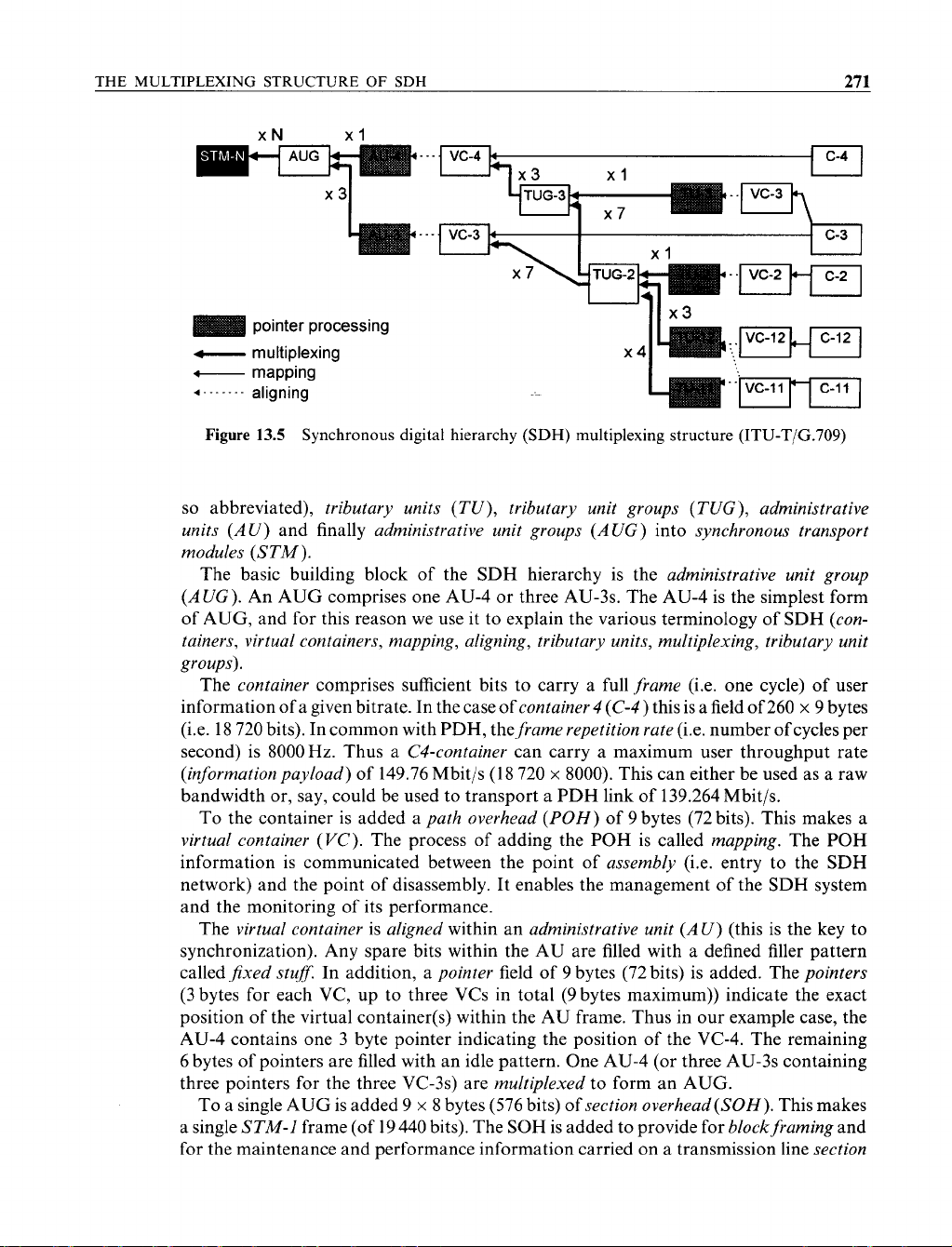
Figure
13.5
Synchronous digital hierarchy
(SDH)
multiplexing structure
(ITU-T/G.709)
so
abbreviated), zyxwvutsrqponmlkjihgfedcbaZYXWVUTSRQPONMLKJIHGFEDCBA
tributary units (TU), tributary unit groups (TUG), administrative
units (AU)
and finally
administrative unit groups (AUG)
into
synchronous transport
modules (STM).
The basic building block of the SDH hierarchy is the
administrative unit group
(AUG).
An
AUG comprises one AU-4 or three AU-3s. The AU-4 is the simplest form
of AUG, and for this reason we use it to explain the various terminology of SDH
(con-
tainers, virtual containers, mapping, aligning, tributary units, multiplexing, tributary unit
groups).
The
container
comprises sufficient bits to carry a full
frame
(i.e. one cycle) of user
information of
a
given bitrate. In the case of
container zyxwvutsrqponmlkjihgfedcbaZYXWVUTSRQPONMLKJIHGFEDCBA
4
(C-4
)
this is a field of 260
X
9
bytes
(i.e. 18 720 bits). In common with PDH, the
frame repetition rate
(i.e. number of cycles per
second) is 8000Hz. Thus a
C4-container
can carry a maximum user throughput rate
(information payload)
of 149.76 Mbit/s (18 720
X
8000).
This can either be used as a raw
bandwidth or, say, could be used to transport a PDH link of 139.264 Mbit/s.
To
the container is added a
path overhead
(POH)
of 9 bytes (72 bits). This makes
a
virtual container
(VC).
The process
of
adding the POH is called
mapping.
The
POH
information is communicated between the point of
assembly
(i.e. entry to the
SDH
network) and the point of disassembly.
It
enables the management of the SDH system
and the monitoring
of
its performance.
The
virtual container
is
aligned
within an
administrative unit (AU)
(this is the key to
synchronization). Any spare bits within the AU are filled with a defined filler pattern
called
fixed stuf.
In addition, a
pointer
field of
9
bytes (72 bits) is added. The
pointers
(3 bytes for each VC, up to three VCs in total (9 bytes maximum)) indicate the exact
position of the virtual container(s) within the AU frame. Thus in our example case, the
AU-4 contains one 3 byte pointer indicating the position of the VC-4. The remaining
6 bytes of pointers are filled with an idle pattern. One AU-4 (or three AU-3s containing
three pointers for the three VC-3s) are
multiplexed
to form an AUG.
To a single AUG is added 9
X
8
bytes (576 bits)
of
section overhead(S0H).
This makes
a single
STM-1
frame (of 19 440 bits). The SOH is added to provide for
block framing
and
for the maintenance and performance information carried on a transmission line
section
![Biến Tần FR-A700: Sổ Tay Hướng Dẫn Cơ Bản [Chi Tiết]](https://cdn.tailieu.vn/images/document/thumbnail/2019/20191130/cac1994/135x160/1741575103503.jpg)
![Xử lý số tín hiệu: Tài liệu thí nghiệm [Chuẩn SEO]](https://cdn.tailieu.vn/images/document/thumbnail/2018/20180821/danhvi27/135x160/7141534836177.jpg)


![Catalogue Insulators: [Thêm từ mô tả phù hợp với nội dung catalogue]](https://cdn.tailieu.vn/images/document/thumbnail/2015/20150608/sincos/135x160/6521433725774.jpg)


![Bài giảng công tắc tơ [mới nhất]](https://cdn.tailieu.vn/images/document/thumbnail/2026/20260506/vispacex_27/135x160/93891778142285.jpg)
![Giáo trình Điện tử tương tự 1: Phần 1 [Mới nhất]](https://cdn.tailieu.vn/images/document/thumbnail/2026/20260506/vispacex_27/135x160/69111778210056.jpg)


