Cordless Telephony and Radio in
the Local Loop (RILL) zyxwvutsrqponmlkjihgfedcbaZYXWVUTSRQPONMLKJIHGFEDCBA
The rapid deregulation of telephone network services taking place during the zyxwvutsrqponmlkjihgfedcbaZYXWVUTSRQPONMLKJIHGFEDCBA
1990s
has brought a
large number of new public network operators to the market, each of which has an interest in
optimizing the cost of customer connection to his network. Much interest, in particular, has been
channelled into radio technologies (so-called ‘radio-in-the-local loop’ or ‘wireless local loop’,
WLL),
as these are seen as a quick and economic way to create new access infrastructure,
bypassing the dependence on the established monopoly operators for ‘last-mile’ connections. In
this chapter we discuss some of the most important technologies in this sector. We also discuss
cordless telephone technology as a means for providing ‘limited mobility’ access
to
fixed
networks. zyxwvutsrqponmlkjihgfedcbaZYXWVUTSRQPONMLKJIHGFEDCBA
16.1
THE DRIVE
FOR
RADIO
IN
THE
LOCAL LOOP
It was historically the case that a monopoly existed on both the public telephone service
and the construction and operation of telecommunications transmission networks. The
state-owned monopoly carrier had the sole right to
lay
cables in the street or construct
radio transmission links. Although competition in public telephone network services
may have been introduced in many countries, there has not necessarily been a
relaxation of the transmission network monopoly. In consequence, the new telephone
carriers (network operators) may be dependent on their strongest competitors for
the supply of all transmission links. Thankfully for the new operators, if a little slowly,
the national transmission monopolies are also being removed. Unfortunately, however,
this does not immediately remove the dependence of the new operators on the ex-
monopoly carrier, because the large base of established lineplant and investment is
difficult for the new carriers to duplicate quickly. The best hope for them lies in the
rapid construction
of
an overlay, radio-based infrastructure.
319
Networks and Telecommunications: Design and Operation, Second Edition.
Martin P. Clark
Copyright © 1991, 1997 John Wiley & Sons Ltd
ISBNs: 0-471-97346-7 (Hardback); 0-470-84158-3 (Electronic)
320 zyxwvutsrqponmlkjihgfedcbaZYXWVUTSRQPONMLKJIHGFEDCBA
CORDLESS TELEPHONY AND
RADIO
IN
THE LOCAL LOOP (RILL)
16.2
FIXED NETWORKS BASED
ON
RADIO TECHNOLOGY
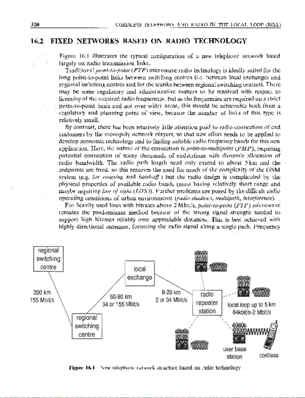
Figure 16.1 illustrates the typical configuration of a new telephone network based zyxwvutsrqponmlkjihgfedcbaZYXWVUTSRQPONMLKJIHGFEDCBA
'
largely
on
radio transmission links.
Traditional zyxwvutsrqponmlkjihgfedcbaZYXWVUTSRQPONMLKJIHGFEDCBA
point-to-point zyxwvutsrqponmlkjihgfedcbaZYXWVUTSRQPONMLKJIHGFEDCBA
(PTP)
microwave radio technology is ideally suited for the
long point-to-point links between switching centres (i.e. between local exchanges and
regionalswitching centres and for the trunks between regional switching centres). There
may be some regulatory and administrative matters to be resolved with respect to
licensing of the required radio frequencies, but as the frequencies are required
on
a strict
point-to-point basis and not over wider areas, this should be achievable both from a
regulatory and planning point of view, because the number of links
of
this type is
relatively small.
By contrast, there has been relatively little attention paid to radio connection of end
customers by the monopoly network players,
so
that new effort needs to be applied to
develop economic technology and to finding suitable radio frequency bands for this new
application. Here, the nature of the connection is
point-to-multipoint
(PMP),
requiring
potential cdnnection of many thousands of endstations with dynamic allocation of
radio bandwidth. The radio path length need only extend to about
5
km and the
endpoints are fixed,
so
this removes the need for much of the complexity of the GSM
system (e.g. for
roaming
and
hand-of)
but the radio design is complicated by the
physical properties of available radio bands (most having relatively short range and
maybe requiring
line ofsight
(LOS)).
Further problems are posed by the difficult radio
operating conditions of urban environments
(radio shadows, multipath, interference).
For heavily used lines with bitrates above
2
Mbit/s,
point-to-point
(PTP)
microwave
remains the predominant method because of the strong signal strength needed to
support high bitrates reliably over appreciable distances. This is best achieved with
highly directional antennas, focussing the radio signal along a single path. Frequency
regional
switching
centre local
2
or
34 Mbitls
repeater
local
loop
up
to
5
km
station
64kbit/s-2 Mbitls
regional
, zyxwvutsrqponmlkjihgfedcbaZYXWVUTSRQPONMLKJIHGFEDCBA
I
\
switching
,
centre
,
station cordless
Figure
16.1
New telephone network structure based on radio technology
FIXED NETWORKS BASED ON RADIO TECHNOLOGY
321 zyxwvutsrqponmlkjihgfedcbaZYXWVUTSRQPONMLKJIHGFEDCBA
bands at 18 GHz, 23 GHz and
‘38
GHz are now allocated for so-called zyxwvutsrqponmlkjihgfedcbaZYXWVUTSRQPONMLKJIHGFEDCBA
shorthaul
microwave
radio systems. The range of systems drops dramatically with higher
frequency, so that while 15 km range is realistic within much of Europe for 18 GHz
systems, 5-7 km is the reckoned range at 38 GHz.
There are many unallocated radio frequency ranges above
40
GHz, but the relatively
short range of radio signals at these frequencies and the need for unimpeded
line zyxwvutsrqponmlkjihgfedcbaZYXWVUTSRQPONMLKJIHGFEDCBA
of
sight
between the antennae (because the radio waves, unlike at lower frequencies, are less
capable of even slight
dzfrraction
around corners and past obstacles). Much attention is
thus focussed on the radio range between
400
MHz and about 40 GHz. There have been
three distinct technological approaches, but the different approaches are likely to
converge. The three approaches are zyxwvutsrqponmlkjihgfedcbaZYXWVUTSRQPONMLKJIHGFEDCBA
0
cordless telephony
0
wireless ISDN
0
shorthaul
point-to-point
(PTP)
and
point-to-ntultipoint
(PMP) microwave radio
We discuss each in turn.
16.3
CORDLESS
TELEPHONES
Cordless telephony is the term used to describe telephone sets connected to the ordin-
ary
(jixed)
telephone network, but in which the handset communicates with the
network by a radio transmission link instead
of
wires. The cradle part of a cordless
telephone terminal acts as a radio transceiver or base
station
to connect a radio path to
the handset, which also acts as a radio transceiver. The base station is connected to the
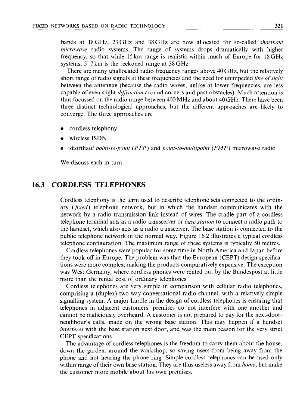
public telephone network in the normal way. Figure 16.2 illustrates a typical cordless
telephone configuration. The maximum range of these systems is typically 50 metres.
Cordless telephones were popular for some time in North America and Japan before
they took off in Europe. The problem was that the European (CEPT) design specifica-
tions were more complex, making the products comparatively expensive. The exception
was West Germany, where cordless phones were rented out by the Bundespost at little
more than the rental cost of ordinary telephones.
Cordless telephones are very simple in comparison with cellular radio telephones,
comprising
a
(duplex) two-way conversational radio channel, with a relatively simple
signalling system. A major hurdle in the design of cordless telephones is ensuring that
telephones in adjacent customers’ premises do not interfere with one another and
cannot be maliciously overheard.
A
customer is not prepared to pay for the next-door-
neighbour’s calls, made on the wrong base station. This may happen if a handset
interferes
with the base station next door, and was the main reason for the very strict
CEPT specifications.
The advantage of cordless telephones is the freedom to carry them about the house,
down the garden, around the workshop,
so
saving users from being away from the
phone and not hearing the phone ring. Simple cordless telephones can be used only
within range of their own base station. They are thus useless away from
home,
but make
the customer more mobile about his own premises.
322 zyxwvutsrqponmlkjihgfedcbaZYXWVUTSRQPONMLKJIHGFEDCBA
CORDLESS TELEPHONY AND RADIO
IN
THE LOCAL LOOP (RILL) zyxwvutsrqponmlkjihgfedcbaZYXWVUTSRQPONMLKJIHGFEDCBA
k zyxwvutsrqponmlkjihgfedcbaZYXWVUTSRQPONMLKJIHGFEDCBA
1::
::: zyxwvutsrqponmlkjihgfedcbaZYXWVUTSRQPONMLKJIHGFEDCBA
W
U’
I
\\M zyxwvutsrqponmlkjihgfedcbaZYXWVUTSRQPONMLKJIHGFEDCBA
Telephone ‘cradle’
I
\
(
base
statlon
1
Mobile
handset
I
up
to
50
metres
Figure
16.2
A
cordless
telephone
From basic cordless telephony (radio path within the end customer’s premises) have
evolved second and third generation technologies in which the base station is shifted to
the public network operator’s site. First came zyxwvutsrqponmlkjihgfedcbaZYXWVUTSRQPONMLKJIHGFEDCBA
telepoint
or
CT2 (2nd generation cordless
telephony). DECT (digital European cordless telephony)
followed.
16.4
TELEPOINT OR CORDLESS TELEPHONE
2
(CT2)
An extension of the idea of cordless telephones is the concept of
telepoint,
French
pointel
or
wide area cordless telephone.
In
telepoint
a new type of digital cordless
telephone is used with a number of base stations. Besides the base station in his house,
the customer has access to public
telepoint
base stations situated in well populated
locations, such as airports, stations, and street corners (much as public payphones are
located today). A
common air interface zyxwvutsrqponmlkjihgfedcbaZYXWVUTSRQPONMLKJIHGFEDCBA
(CAZ)
ensures compatibility of mobile handsets
from various manufacturers with the
base
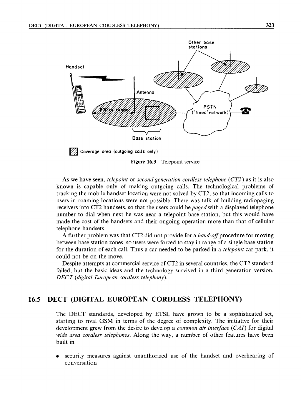
stations of the public network. Standing
within 50-200m of a telepoint, a caller with a telepoint handset is able to make
outgoing calls into the public switched telephone network in a similar way to a cellular
radio customer making an outgoing call, except that he may not move from one base
station to another during the call. Incoming calls, however, are not possible other than
at the home base station (i.e. the subscriber’s home). Telepoint hardware includes a
mobile handset and a number of base stations, each connected directly to the public
switched telephone network, as Figure
16.3
illustrates.
To
make a call, the handset sends a signal, including a special handset identity code,
over a control channel to the base station, which confirms the identity and authorization
of the user, and then allocates a radio channel in a way similar to that used in cellular
radio. Onward connection of the call is made directly via the
PSTN,
applying dial tone,
collecting dialled digits, etc., while the base station records call details for later billing of
the customer. (There is one exception to this, and that is when the customer has installed
a private base station in his own premises. In this case the customer pays for public
network calls in the normal way as recorded by the
PSTN
operator.)
DECT (DIGITAL EUROPEAN CORDLESS TELEPHONY) zyxwvutsrqponmlkjihgfedcbaZYXWVUTSRQPONMLKJIHGFEDCBA
323 zyxwvutsrqponmlkjihgfedcbaZYXWVUTSRQPONMLKJIHGFEDCBA
Other base
stations
Handset
‘fixed’network)
Base station
Coverage area (outgoing calls only)
Figure
16.3 Telepoint
service
As we have seen, telepoint or second generation cordless telephone (CT2) as it is also
known is capable only of making outgoing calls. The technological problems of
tracking the mobile handset location were not solved by CT2,
so
that incoming calls to
users in roaming locations were not possible. There was talk of building radiopaging
receivers into CT2 handsets,
so
that the users could be paged with a displayed telephone
number to dial when next he was near a telepoint base station, but this would have
made the cost of the handsets and their ongoing operation more than that of cellular
telephone handsets.
A
further problem was that CT2 did not provide for a hand-oflprocedure for moving
between base station zones, so users were forced to stay in range
of
a single base station
for the duration of each call. Thus a car needed to be parked in a telepoint car park, it
could not be on the move.
Despite attempts at commercial service of CT2 in several countries, the CT2 standard
failed, but the basic ideas and the technology survived in a third generation version,
DECT (digital European cordless telephony).
16.5
DECT (DIGITAL EUROPEAN CORDLESS TELEPHONY)
The DECT standards, developed by ETSI, have grown to be a sophisticated set,
starting to rival
GSM
in terms
of
the degree of complexity. The initiative for their
development grew from the desire to develop a common air interface (CM) for digital
wide area cordless telephones. Along the way, a number of other features have been
built in
e
security measures against unauthorized use
of
the handset and overhearing of
conversation


![Biến Tần FR-A700: Sổ Tay Hướng Dẫn Cơ Bản [Chi Tiết]](https://cdn.tailieu.vn/images/document/thumbnail/2019/20191130/cac1994/135x160/1741575103503.jpg)
![Xử lý số tín hiệu: Tài liệu thí nghiệm [Chuẩn SEO]](https://cdn.tailieu.vn/images/document/thumbnail/2018/20180821/danhvi27/135x160/7141534836177.jpg)


![Bài giảng Nhập môn Kỹ thuật điện [chuẩn nhất]](https://cdn.tailieu.vn/images/document/thumbnail/2025/20251208/nguyendoangiabao365@gmail.com/135x160/60591765176011.jpg)