* Corresponding author.
E-mail addresses: fmaloqla@hu.edu.jo (F. M. AL-Oqla)
© 2019 Growing Science Ltd. All rights reserved.
doi: 10.5267/j.esm.2019.4.001
Engineering Solid Mechanics 7 (2019) 121-130
Contents lists available at GrowingScience
Engineering Solid Mechanics
homepage: www.GrowingScience.com/esm
Experimental investigation and numerical prediction for the fatigue life durability of austenitic
stainless steel at room temperature
M. A. Khairula, S. M. Sapuana, Faris M. AL-Oqlab* and E. S. Zainudinc
aMechanical Engineering Section, Universiti Kuala Lumpur, Malaysia France Institute, Section 14, Jalan Teras Jernang, 43650 Bandar Baru Bangi,
Selangor, Malaysia
bDepartment of Mechanical Engineering, The Hashemite University, Zarqa 13133, Jordan
cInstitute of Tropical Forestry and Forest Products (INTROP), Putra Universiti, 43400 UPM Serdang Selangor, Malaysia
A R T I C L EI N F O A B S T R A C T
Article history:
Received 26 December, 2018
Accepted 26 February 2019
Available online
11 April 2019
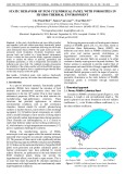
This work investigated and predicted the fatigue life durability of Austenitic Stainless Steel 316L
at room temperature due to its importance in plant industries worldwide. Modelling and
simulations were performed to clarify the fracture as well as stress distribution using integrated
mechanism. Experimental fatigue validations were also carried out to demonstrate the effect of
various fatigue life parameters. Various loading conditions with variable load amplitudes were
validated utilizing a frequency of 5 Hz and a stress ratio of 0.1. The accuracy of the simulation
results were also verified based on the experimental data. High consistencies between the predicted
fatigue life and the experimental results were achieved which increases the validity of the built
model.
© 2019 Growin
g
Science Ltd. All ri
g
hts reserved.
Keywords:
Fatigue life
Composites
Stainless steel
Modelling
Prediction
1. Introduction
Due to the tremendous need for engineers to properly select and use the most appropriate function as
well as economic material type to achive suscessful design, further investigations on the materials
behaviour and fracture under different conditions are still desired (Yıldız et al. 2011, Mughrabi 2001,
Huynh et al. 2008, Khairul et al. 2017). The new available types of modern materials including both
traditional and green ones (Al-Oqla et al. 2014; 2015a,b; Al-Oqla and Sapuan 2015) which make the
selection of the appropriate material type a sophisticated problem (Al-Oqla and Sapuan 2018; Al-Oqla
2017; Al-Oqla and Salit 2017 Al-Oqla et al. 2015c). A few decades ago, the prevailing viewpoint was
brittle material did not experience fatigue (as brittle materials have limited dislocation motion); however,
brittle materials exhibit both mechanical fatigue and thermal fatigue under repetitive loadings. In
addition, there are still various failures of components in many heavy industries in global market,
including the fabrication stage of components. This phenomenon is mainly due to the development of
natural defect that is not completely avoidable, such as inhomogeneity and non-metallic inclusions (Al-
Oqla et al., 2019; Fares et al., 2019). In heavy industries such as power plant, aerospace field, and oil and
gas industries, the component that is made of material such as 316L stainless steel is frequently used in

122
both room and high temperature conditions. Many stainless steel grades have been employed to satisfy
the performance requirements in many fields, such as aerospace, automotive, medical, electronic, and
energy industries, as well as oil and gas industries. Different types of austenitic stainless steel is currently
being employed in various industries, such as the oil and gas industries and nuclear industries, i.e., type
304, 309, 316L, 321, 347, 348, and 316LN, whereas stainless steel 316L is more convenient considering
its advantages. The elevated temperature and stress-creep the deformation of component engineering that
has given significant impact to the world (Mughrabi 2001; Hayhurst 1972; Finnie and Heller 1959;
Bendersky et al. 1985). Several researchers have studied and investigated the factors that contributed to
the cumulative damage mechanisms as they are significant in considering the effect of diversity in types
of creep damage on high stress fatigue behaviour, shape, and high temperature. Stainless steel
experienced severe thermal cycles in high heat flux application in transportation oil systems. Many
researchers have focused on the service life prediction and extension of tubular steel, which was
challenging due to the geometric shapes of specimens and the complexity of the phenomena. Concerning
to determination and characterization of accuracy of a life prediction, both the upper bound and the lower
bound were introduced as main aspects of engineering components at elevated temperatures. However,
no specific life prediction model had gained global acceptance among the majority of plant industries. It
was discovered that each industry performed separate life predictions according to the situation and
application. The notable difficulty in the prediction on any material was accounting for the contributions
by creep and/or environmental attack of the fatigue process (Mughrabi 2001; Hayhurst 1972; Finnie and
Heller 1959; Bendersky et al. 1985). Several investigations have been performed to study the effect of
creep, temperatures on the mechanical characteristics of steel. Tabuchi and co-workers (2003) have
mentioned that the high strength steels are usually operated at room temperature and stresses below the
yield strength and failure would occur for such types of steel due to the influences of creep stresses as
well as other environmental factors. On the other hand, Zheng et al. (2005) have reported that the
petroleum and natural gas transmission that utilize stainless steel as pipelines will contain defects and
flaws from the manufacturing installation and servicing process. These defects could influence the safety
of pipelines and even reduce their service life which might goes to massive financial costs and endanger
the ambient ecological circumstances. In the damage tolerant design approach for any structural
component, analysis and testing should be performed to demonstrate whether any pre-existing defects in
the material will grow to catastrophic proportions within a time span of half the inspection interval. This
testing necessitates an accurate prediction of the fatigue crack growth rate for any given service
conditions that pertain to the criticality of the loading and temperature conditions for the component.
Therefore, considerable effort towards an understanding of crack growth behaviour under fatigue loading
with elevated temperatures and the relevance of these mechanics to the failure of a structure caused by
creep, fatigue and the environment’s effects, such as oxidation is crucial Fan et al. (2005). Also creep-
fatigue, oxidation fatigue and creep-fatigue-oxidation damage to components were studied based on the
specific materials and loading conditions Beden et al. (2009). Moreover, several studies o suggested
damage models based on endurance limit reduction were proposed to study the fatigue behaviour of steel.
The creep-fatigue evaluation methods have been proposed based on fatigue life and failure mechanisms
under creep-fatigue loading. Two main life prediction methods, namely, an empirical “linear damage
summation” method and a mechanism-based “cavitation damage” model were frequently used (Fan et
al. 2006). These models were nonlinear and account for the load sequence effect (Marquis et al. 2013).
Coarse slip model on the other hand was also considered to be an avalanche of fine movements, whereas
slip lines appear as parallel lines or bands within a grain when viewed perpendicular to a free surface
(Niesłony et al. 2012). However, none of these models considered the load interaction effect (Stephens
et al. 2000).
Consequently, the estimation of steel life and verifying the effectiveness of particular parameters and
factors on the steel structures to improve the development of this modern arena are still required.
Moreover, proper investigations and simulating various conditions that affect the life span of such types
of materials are of paramount importance. Thus, the objective of this work is to properly investigate the
effect of various parameters that affect the life span of Austenitic Stainless Steel 316L due to cyclic

M. A. Khairul et al. / Engineering Solid Mechanics 7 (2019)
123
loading and to predict such life using a FEA model as well as to validate the prediction with experimental
fatigue tests to demonstrate such effects under various loading conditions.
2. Materials and Design
Experimental specimens from austenitic 316L stainless steel were supplied and fabricated by S.N
Machinery Services Sdn. Bhd. in Malaysia to be utilized in the fatigue’s experiment. The specimen
provided was a 26.7 mm diameter cold drawn bar, annealed at 1100oC and water quenched and was
fabricated to be an hourglass shaped specimen which has threaded ends inside for gripping purposes in
accordance to the ASTM 606 for fatigue test. The grain size was 80 m
for 316L stainless steel for the
heat treatment. To collect the data for the fatigue test, seven data plots were sufficiently adequate, as
recommended by ASTM E606-92 (1998) to establish an S-N curve. The specimens were subjected to
several different maximum stress levels with an initial stress of 0.9 YS (90% of the yield strength) of the
materials followed by 0.80 YS, 0.70 YS, 0.60 YS, 0.50 YS, 0.40 YS and 0.30 YS. The magnitude of load
was inserted and the distribution of load was selected to be uniform. The periodic was chosen as the type
of amplitude of a sinusoidal. The time span was set as step time, circular frequency, 2πf with 31.42 as
the frequency was set to 5Hz, starting time and initial amplitude as zero. The specimens were subjected
to repetitive loads to impose a limit of fatigue life for 107 cycles due to the cost and time
constraint/limitation.
3. Fatigue Experimental Work
Fatigue is considered one of the most serious failure modes of materials due to the effect of repeated
cyclic stresses for a period of time. It is influenced by various factors, for instance, size, shape and design
of the component, conditions of the surface or operating environment. Seven specimens were involved
in the fatigue test with stress ratio of 0.1 and 5 Hz of loading frequency in the investigation of the effect
of such factors on the Austenitic Stainless Steel 316L at room temperature. Fatigue tests were conducted
using Hydraulic Universal testing Machine (model: Instron 8802) with 250 kN load capacity. The fatigue
machine and set-up experiment with software were shown in Fig. 1. The hourglass specimens of stainless
steel with gauge length of 100 mm were used, and results were measured using an extensometer attached
at the machine. Test on the Specimens were conducted until rupture stage. The final results were taken
as load versus cycles on specimens. Tests were carried out under stress controlled displacement
conditions, where sinusoidal waveform is subjected to seven specimens to increase the reliability of the
study.
Fig. 1. Fatigue Machine System for the Conducted Experiments.
Load Cell
Actuator
Data
Acquisition
Software
Controller
Specimen of
Type 316L
Stainless
Steel
Hydraulic Cross
System

124
4. Simulations
A model has been developed using CATIA V5 software. Then, it was imported to ABAQUS software
to perform the simulation analysis. This study was carried out to predict the durability of stainless steel
316L steel using Finite Element Analysis (FEA). Fatigue life correlations were incorporated into FEA
parameters (Yıldız et al. 2011). The simulated results were validated with experimental data, where the
differences between the predicted fatigue life and the experimental fatigue life were discussed. The model
was meshed before job analysis was carried out. Upon completion, the post processing results of loads
versus cycles were compared with the experimental results as they exhibit well interpretation of the load-
cycles responses with experimental at the end of simulations. Specimens were set by elastic materials that
are of homogeneous type. The mechanical properties such as density, yield strength, ultimate strength,
and Poisson’s ratio were inserted into the FEA for initial step as basic properties of specimens. Boundary
conditions were used to constrain the model. Boundary conditions for the axisymmetric model were
applied, where symmetry on the nodes located at the centre of the gauge length was applied with
prescribed displacements on the top part of the model and a predefined temperature as 27oC field along
the gauge section on each element. Such constraints were able to create simply supported or fixed
conditions. The model utilized axisymmetric eight-node elements. Symmetry of the model was assumed
and only the upper half of the specimens was needed to be modelled. The magnitude of the load was
inserted and the distribution of load was selected to be uniform. The values were determined according
to the percentage of ultimate strength such as 90%, 80%, 70%, 60%, 50%, 40%, and 30% of ultimate
strength. The periodic was chosen as the type of amplitude of a sinusoidal. The time span was set as step
time, circular frequency, 2πf with 31.42 as the frequency was set to 5Hz, starting time and initial
amplitude as 0. A tubular cylindrically shaped specimen was designed for the fatigue test with a
minimum waist of 19.58 mm, a gage length of 40 mm, an outside diameter of 26.7 mm, and a wall
thickness of 2 mm. The technique to mesh a model or model region, in which pre-established mesh
patterns was applied to particular model topologies. This FE model represents the gauge section of the
rounded specimens, and the mesh density provided suitable aspect ratios and accurate numeric results.
Fig. 2: Flow chart of the conducted simulations
Choosing the type
of FE anal
y
sis
Generation of mechanical
properties data set up the
a
pp
lied stress re
q
uired
Generating model attributes;
materials model, type of elements,
constraints, etc.
Subsequent pre-processing
number of cycles according
to current stress
Solution update the cycle number
accordin
g
to current stress level
Findin
g
errors
Results
Errors?

M. A. Khairul et al.
/ Engineering Solid Mechanics 7 (2019)
125
The model considered a tubular specimen that was subjected to an external stress loading and a
temperature of 27°C. The test of the model compared the behaviour of the model with the actual problem
and its environment. This work focused on the formulation of the model for this system/problem and
identified as well as collected the data required to test the model. It also determined the randomness of
the input parameter, the number of experiments, the run period and the methodology. Fig. 2 demonstrates
the flow chart in running the simulations in order to obtain the cycles to failure of specimen in the current
FE analysis.
5. Results and Discussion
The fatigue data of constant amplitude load fatigue analysis with load ratio of 0.1 and frequency of 5
Hz was applied on AISI Type 316L stainless steel specimen. The results of Von Mises stress after the
maximum cycles of 8405 was considered when reached to the maximum stress of 315.5 MPa as the
highest stress concentration. The failure mechanism map that defines the regions of fatigue failure, creep
failure and creep fatigue interaction is shown in Fig. 3.
Fig. 3. Failure mechanism map that defines the regions of fatigue failure, creep failure and creep
fatigue interaction
Besides that, the region also experienced maximum strain as the maximum stress exerted on the region
is stretched out. Thus, the region with the highest stress and strain concentration area will elongate and
form crack until it break after exceeding ultimate strength. This statement is supported by Huynh et al.
(2008), where most cracks were more susceptible to occur in the high tension zones, normally at a flaw
or defect in the base material. This was inconsistence of the expected trend, where the crack is a result
of fatigue occurring in the high stress concentration area (Huynh et al., 2008; Maeng & Kang 1999). On
the other hand, both ends of specimen with blue colour region undergone the minimum stress and strain,
as one end is fixed, whereas the load is applied on the other end. According to the experimental results,
the maximum stress was also exerted on the same region. This is because, the thickness of the middle
region was the smallest with difference of 3.56 mm compared to other areas and the curve geometry at
the region which made it easier for high stress concentration to occur. So, that region is more susceptible
to fatigue when cyclic load is applied. Thus, this has proven that the result from the FEA was reliable.
Furthermore, as the 316L stainless steel is a ductile
material where it is able to yield under continuous
loading at normal temperature, the stress-strain data that was taken from node 1202 in the specimen
indicates that it fell under the stress concentration region. A comparison of stress-strain between
simulated and experimental cases was as demonstrated in Fig. 4. The yield strength in the simulation
and experimental analysis are 463 MPa and 332 MPa, which has a moderate difference, about 131 MPa.
According to Velay et al. (2002), there are several aspects that is useful to explain the differences between