
REGULAR ARTICLE
Heat exchanger design studies for molten salt fast reactor
Uğur Köse
1
, Ufuk Koç
1
, Latife Berrin Erbay
2
, Erdem Öğüt
3
, and Hüseyin Ayhan
1,*
1
FİGES Engineering, R&D Center, Nuclear Technology Department, 06690 Ankara, Turkey
2
Eskişehir Osmangazi University, Mechanical Engineering Department, 26040 Eskişehir, Turkey
3
FİGES Engineering, Teknopark-İstanbul, Additive Manufacturing Systems Department, 34906 İstanbul, Turkey
Received: 15 February 2019 / Received in final form: 8 July 2019 / Accepted: 20 September 2019
Abstract. In this study, conceptual design for primary heat exchanger of the Molten Salt Fast Reactor is made.
The design was carried out to remove the produced heat from the reactor developed under the SAMOFAR
project. Nominal power of the reactor is 3 GWth and it has 16 heat exchangers. There are several requirements
related to the heat exchanger. To sustain the steady-state conditions, heat exchangers have to transfer the heat
produced in the core and it has to maintain the temperature drop as much as the temperature rise in the core due
to the fission. It should do it as fast as possible. It must also ensure that the fuel temperature does not reach the
freezing temperature to avoid solidification. In doing so, the fuel volume in the heat exchanger must not exceed
the specified limit. Design studies were carried out taking into account all requirements and final geometric
configurations were determined. Plate type heat exchanger was adopted in this study. 3D CFD analyses were
performed to investigate the thermal-hydraulic behavior of the system. Analyses were made by ANSYS-Fluent
commercial code. Results are in a good agreement with limitations and requirements specified for the reactor
designed under the SAMOFAR project.
1 Introduction
The power production from the thermal power plants is
possible through a thermodynamic cycle. The heat
produced in the core of a nuclear reactor by a fissionable
fuel is transported into a coolant. Then, heat is transferred
to the working fluid by using heat exchangers (HX). This
thermodynamic cycle is mainly either Rankine or Brayton
cycle. Molten Salt Reactors (MSRs) have gained impor-
tance and different initiatives have been brought. A
sustainable secure nuclear future based on Thorium
Molten-Salt Nuclear Energy Synergetics (THORIMS-NES)
[1–5] and a conceptual design of a Stirling engine with the
MSR reactor [6]aretypicalexamples.
In MSRs, the heat transfer between the radioactive
liquid fuel salt and the secondary salt or between this salt
and the conversion working fluid is ensured by heat
exchangers. In the MSRs, one of the most important
equipment after the core is the heat exchanger. Therefore,
the design of the heat exchangers for MSRs is a crucial task.
The number of heat exchangers varies depending on the
design of the core, the number of loops, and the type of the
power cycle. The primary loop and the secondary loop heat
exchangers, preheaters, steam generators, after heaters,
condensers and others are all different types of heat
exchangers with certain vital functions in the MSR cycle.
They are the main components of the plant due to not only
their functions and the numbers but also as their different
conditions and tradeoffs depending on the location and
connections in the main cycle.
The heat exchanger design is also strictly subjected to
change with the properties of fluids flowing through the
heat exchanger. The type of the coolant and working fluid
should be determined in advance. In the MSRs, the
principle liquid fuel is preferred as a molten salt consisting
of eutectic salts and operating at temperatures of 600–
800 °C including LiF-BeF
2
-ThF
4
for the case of thorium
after many researches. The problem is the thermo-physical
properties of these eutectics. When LiF-BeF
2
-ThF
4
is
considered, it is found that two different mole percentages
can be used. In the first salt, the mole percentages of LiF-
BeF
2
-ThF
4
are 72.7–15.7–11.6 whereas in the second one,
percentages will be 70.11–23.88–6.01 [7]. Such a small
difference causes dramatic changes in the properties. For
example, between 553 and 673 °C, the viscosity of the first
salt varies between 14.1 and 7.74 cp. Whereas the viscosity
of the second salt at the temperatures between 557 and
653 °C varies from 12.59 to 7.30 cp [7]. When the viscosity is
concerned, the 3rd and 4th degree polynomials exist for
these salts, respectively. This gives an idea how difficult is
the design of a heat exchanger system in terms of such
unique properties of salts. The properties of fluids therefore
indicate an important and serious step in the design study.
*e-mail: huseyin.ayhan@figes.com.tr
EPJ Nuclear Sci. Technol. 5, 12 (2019)
©U. Köse et al., published by EDP Sciences, 2019
https://doi.org/10.1051/epjn/2019032
Nuclear
Sciences
& Technologies
Available online at:
https://www.epj-n.org
This is an Open Access article distributed under the terms of the Creative Commons Attribution License (http://creativecommons.org/licenses/by/4.0),
which permits unrestricted use, distribution, and reproduction in any medium, provided the original work is properly cited.

The main design purpose is to supply the exact heat
transfer at a given time duration during operation. The
total heat transfer area between the fluids, the overall heat
transfer coefficient and temperature differences of fluids in
both sides are the main parameters to be known on one side
and to be determined on the other side. They are mutually
dependent items.
For MSFR, that needs much larger heavy elements
inventory than thermal MSR, there is an incentive to
minimize the fuel salt volume, a limited fraction of which
being in the heat exchangers. Therefore, the rate of heat
transfer in the heat exchanger should be augmented and
hence compact structures with high heat transfer areas per
unit volume are necessary. However, enhancement in heat
transfer will adversely affect pressure loss, which is related
to pump design.
As it can be deduced from these explanations, the
design of heat exchangers is critical. The design studies of
the heat exchangers obviously require attention for
complete and successful operation and it is needed that
design parameters must be strictly defined to get most
efficient heat transfer through the MSR. The previous
efforts on the heat exchanger design for MSRs are
summarized first in the following section. Then the design
studies of the primary heat exchangers of Molten Salt Fast
Reactor (MSFR) are carried out by FİGES under the
SAMOFAR Project are going to be presented.
2 Historical development of the HXs
for MSRs
The number and size of heat exchangers in MSR plants
depend on the physical properties of the fluids, power level
and the type of the thermodynamic cycle preferred. In the
Brayton cycles, two or three to eight intercooling stages are
used, which means that there are many HXs as in the multi-
reheat steam circulations in Rankine cycle.
The thermodynamics of MSRs is well established since
the first studies carried by Oak Ridge National Laboratory
(ORNL) in 1950s. The design experience on the HXs used
in MSRs lies to the initial development of MSRs to provide
a heat source to a jet engine in the US Nuclear Aircraft
Development Program (NAP) in 1950s (or it is mentioned
as Aircraft Nuclear Propulsion ANP Program [8]).
Following the cancellation of the aircraft program, MSR
was investigated between 1960s and 1970s up to the
cancellation of the program by US ultimately. Due to over
20-yr effort, HX design studies of ORNL deserves attention
before practicing the advanced design studies for MSFR.
The HXs which are used in the Homogeneous Reactor
Test (HRE-2) at ORNL [9] were manufactured by
considering typical shell & tube HX design principles.
For the primary and secondary loops, eight fuel to sodium
HXs and sodium to steam HXs were all shell & tube type. In
order to get an idea about the design, it is better to give
some numerical values for some parameters. The main
characteristics of the HRE-2 steam generators had the heat
transfer area of 44.6 m
2
with the rate of heat transfer of
5000 kW. The tube side diameter of 0.009525 m was used
with the velocities of 20.42 and 3.44 m/s on the shell side
and tube side, respectively. The inlet and exit temperatures
for shell and tube sides were 82.2–443.9 °C and 256.9–
300.0 °C, respectively. The shell & tube steam generators in
HRE-2 were thermal cycled with diphenyl as the heating
medium. HRE-2 spare steam generator [9] contained
eighty-eight 5/8 in OD, 0.095 in thick, type-347 stain-
less-steel tubes having multiple U-bends.
A salt-to-gas primary HX design study was carried [10]
for determining the problems and the effects of varying HX
tubing size, coolant inlet temperature, coolant pressure
level, allowable salt pressure drop and uranium enrichment
of the molten salt. For this design study, a reactor of
640 MWth and electrical output of 275 MW was
considered. The type of the HX was a cross, countercurrent
flow arrangement with molten salt having four serpentine
passes across the gas stream. Inconel was the material for
tubing and circumferential fins.
Two experimental reactors were built and successfully
operated. These were the Aircraft Reactor Experiment
(ARE), the first MSR with 2.5 MWth, and the Molten Salt
Reactor Experiment (MSRE), with 8 MWth. MSRE was a
first experimental step to study a large Molten Salt
Breeder Reactor (MSBR) and should have been followed
by the Molten Salt Breeder Experiment (MSBE), a full-
scale model of the MSBR used at 100–150 MWth [8,11]
that has never been built. Some test loops with molten
salts were operated for hundreds of thousands of hours.
Materials of construction were code qualified to 750 °Cand
a detailed conceptual design of a 1000 MWe MSBR was
developed. The history of HXs for MSRs is parallel to
those efforts.
The HX in the primary fuel circuit of Molten Salt
Reactor Experiment (MSRE) of 10 MWth limited to about
7.5 MWth was designed in 1961, fabricated in 1963 and
installed in 1964. After some modifications, the HX has
been operated for approximately 14000 h with molten salt
temperatures from 537.8 to 662.8 °C without any leakage
and no change in the performance [12]. The HX of a shell &
tube type with U-tube configuration was chosen since it is
the best design which satisfied the requirements and
minimized the thermal expansion problems. The fuel flows
through the shell side of the primary HX and the coolant
salt circulates at the tube side. HX was tested with water
but there were excessive vibrations and pressure drop. It
was noted that [12] to alleviate the tube vibrations and
lower the shell side pressure drop, 4 outermost U-tubes and
4 associated tie bars were removed and plugs were welded
into the 8 resulting tube stub ends, and into all the resulting
holes in the baffle plates since the U-bends vibrated quite
severely.
The heat-exchange system for one conceptual 1000 MWe
MSBR has been studied [13]. A modular-type design having
four separate but identical reactors with their own salt circuits
was used by employing a two-region fluid-fuel concept in
which fissile materials were inthe core and fertile material was
in the blanket streams. Five types of HXs were mentioned in
each loop, namely, one primary fuel salt to coolant salt
exchanger, one blanket salt exchanger, four boiler superheater
exchangers, two steam re-heater exchangers, and two reheat
steam preheaters to transfer the heat in the fuel and blanket
salts to the coolant salt and from the coolant salt to the
2 U. Köse et al.: EPJ Nuclear Sci. Technol. 5, 12 (2019)

supercritical fluid. They were all designed as shell & tube HXs
as two-pass vertical exchangers with disk and doughnut
baffles.
In the units for a 1000 MWe MSR plant [14], there
were a boiler superheater and two reheaters designed as
shell & tube HX. Besides many different attempts to
design boilers for MSR plants with some serious
disadvantages have been made, a reentry tube boiler
type was proposed to satisfy all the major requirements for
the steam generators of liquid metal and MSR power
plants. The salt was NaBF
4
, which mainly determined the
tube length required. It was added that plant layout
studies in a conceptual design for the net electrical output
of 1000 MW favored the use of six steam generators each
coupled to one of six fuel-to-NaBF
4
HXs in the Rankine
cycle. Therefore, the design was an illustrative for the
analysis of the full-scale steam generator. In this design,
the thermal resistance of the inner tube wall at the lower
end was increased by using double-walled tube with a gap
that is going to be vented and filled with steam.
The steam generator with 349 parallel vertical
U-shaped HX with one shell pass and one tube pass was
simulated [15] on an analog computer to understand the
dynamic responses of the components. For the dynamic
analysis, a single water tubular channel surrounded by a
salt annular channel was taken as a model. The design
studies of HXs should obviously include such dynamic
analysis.
A U-tube HX as one of the six fuel to inert salt HXs in a
2200 MWth reference design reactor was analyzed [16]. The
tube bundle had the tubes in an equilateral triangular
layout and the fuel salt flows axially around the tubes on
the shell side and the inert salt in counter flow inside the
tubes. The analyses were concentrated on the parametric
effects to the HX design to optimize the system design. In
order to minimize the fuel inventory in the HX, which is a
dependent variable of major interest, tube size is decreased,
the fuel pressure drop is increased, it is decided that the salt
can be FLiNaK instead of NaBF
4
, and the temperature
difference between the fuel and inert salt is increased.
In MSR plants, heat exchangers of the shell & tube type
have been distinguished so far. The well developed
technology and widely used standards of the shell & tube
type HXs are the main reasons for their preferability.
Mainly conventional shell & tube with U-tubes and shell &
tube with U-tubes in a U-shaped casing for supercritical
pressure steam were proposed but the excessive tempera-
ture difference between salt and steam, the possibility of
freezing of salt and unstable boiling were major problems in
these types [14,17]. The temperature differences between
inlet and outlet fluid during steady-state operation is
limited but large temperature changes may occur at
transient cases. Therefore, thermal stresses become a major
design consideration too.
The main disadvantages of a shell and tube heat
exchanger are low heat transfer efficiency, low heat transfer
surface area density. Besides, the main advantages of plate
type heat exchanger are less erosion-corrosion issues
compared to shell and tube heat exchanger, wide choice
of materials (important for corrosion and erosion of the
salts), low salt inventory, high turbulence and true counter
flow lead to an efficient heat transfer [18,19]. In this study,
it has been focused on the plate-type heat exchanger design
to overcome these problems.
By looking at these historical design efforts for the
design of HXs for molten salt reactors, the HXs were
specified the existing technology and under the Standards
of Tubular Exchanger Manufacturers Association (TEMA)
and ASME. Today, technology presents well developed
alternative compact types, like parallel plate HXs. It is
obviously deduced that many critical parameters and the
relations between these parameters must be strictly defined
and considered to get an optimized system design as a
whole. For the system designed, all boundary and
operation conditions were limited and studies were carried
out. All variables that affect the performance of the system
were studied parametrically.
3 Design studies for SAMOFAR project
In this section, the design methodology and the proposed
type will be explained. The type of HX is determined
according to the design criteria for the adopted conceptual
MSFR. The MSFR, which is designed under SAMOFAR
project, has the thermal capacity of 3000 MW. There are
16 HX located outside of the cylindrical reactor [20–23].
Therefore, the thermal capacity of each heat exchanger
is approximately 190 MW. Since a compact heat exchanger
is intended, it has been focused on plate type heat
exchangers. Moreover, fuel residence time will be short,
pressure drop amount will be small and also the maintenance
procedure is easier for the plate type HX. The design of
the heat exchanger plates was carried out in a flat and
corrugated form. Analyses were conducted in such a way
that there were countercurrent flow for both designs. Since
the circulation time of the fuel salt in the system should
be kept as short as possible [21,22], the single-pass
heat exchanger design, rather than the multi-pass, is
considered.
3.1 Design procedure
In the heat exchanger design process, there are several
important requirements such as thermal-hydraulic design,
mechanical design, material selection, manufacturability,
maintenance and safety. The heat exchanger is expected to
meet certain criteria such as thermal capacity, hydraulic
behavior and material strength, especially, and to have the
most suitable form such as compactness, manufacturability
and maintainability. This study focuses on the thermal-
hydraulic analyses of the heat exchanger. The design
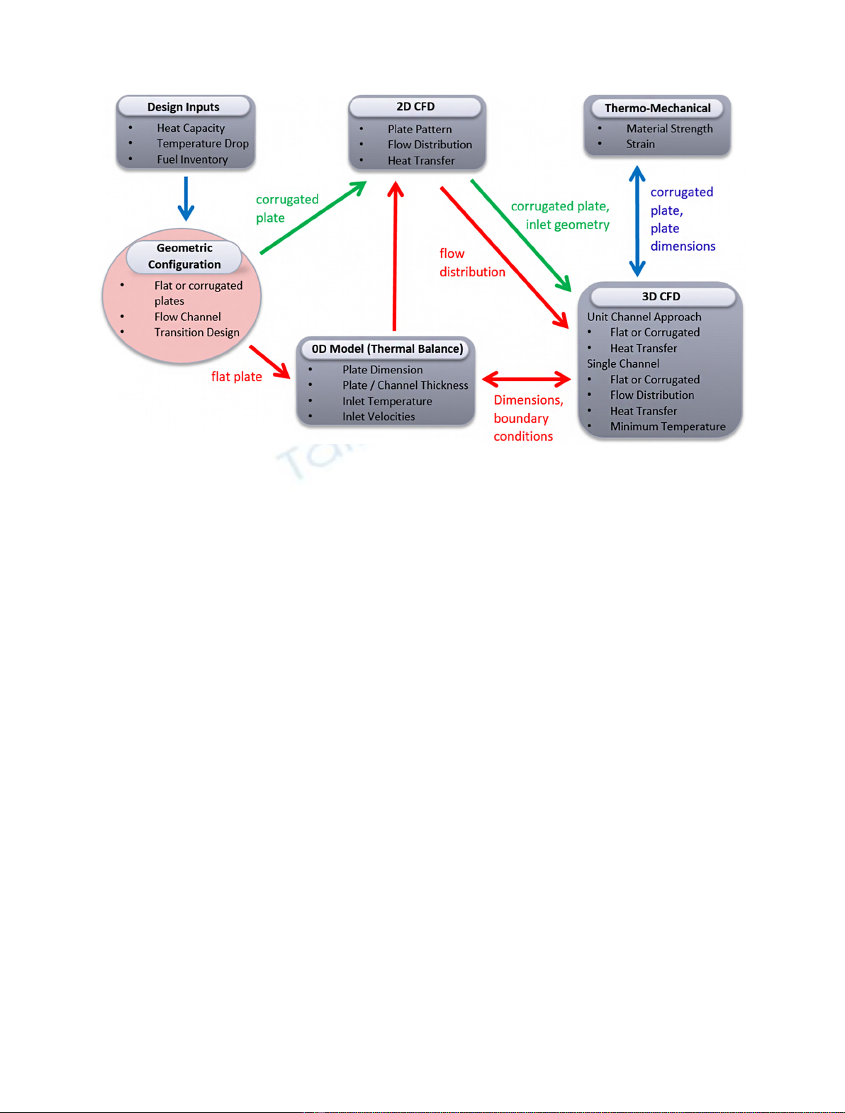
procedure created for the study is given in Figure 1. One-
way arrow represents forward process and two-way arrow
represents iterative process. 3D CFD results were used to
correlate the dimensionless model (0D Model). 3D CFD
studies and mechanical analyses provide lots of feedback to
each other.
In the flat plate design, parameters that affect the
performance of the system such as channel spacing, plate
thickness, fluid inlet velocities and inlet temperatures have
been investigated by using a 0D Model with the solver
U. Köse et al.: EPJ Nuclear Sci. Technol. 5, 12 (2019) 3
created in MATLAB platform. For the decision of
geometric configuration, 2 and 3 dimensional (2D&3D)
computational fluid dynamics (CFD) analyses were
performed. The flow distribution and thermal performance
of the system were examined in detail. In the 2D study,
analyses were performed to ensure that the fluids were
uniformly and evenly distributed within the channel.
Geometric parameters determined in 0D model were used
in 2D studies. In 2D analyses, collector locations, entrance
geometry type and flow separator position and dimensions
were studied. After achieving the ideal combinations, 3D
studies were performed using 2D CFD results and 0D
Model parameters like plate dimensions and inlet con-
ditions. In 3D CFD studies, the thermal behavior of the
system was investigated in detail. Bulk temperatures, local
minimum temperatures and temperature gradient distri-
butions were investigated.
In the corrugated plate design, the effect of design
parameters such as groove depth, groove opening, channel
width and fluid velocities were investigated by using 2D
CFD analyses. Then the detailed 3D CFD analyses were
performed to investigate the flow characteristics as well as
the thermal behavior.
3.2 Preliminary studies
For heat exchanger design, a program (script) was written
in MATLAB and the user interface was prepared to
determine the geometric configuration. This program
provides a dimensional comprehension of the desired
logarithmic temperature difference in a flat plate without
separators. The model was initially considered ideal. For
example, collectors are properly positioned, flow is
uniformly distributed and inlet effects are ignored. With
the outputs of this program, the dimensions of the flat plate
were roughly decided and the CFD studies were continued.
In line with the outputs from MATLAB, 3D unit-channel
CFD analyses were performed on a flat plate with no
brackets by accepting that the flow is evenly distributed.
The CFD results for bulk temperatures and system height
were compared with the results of the MATLAB program.
Considering the differences, the 0D Model was corrected by
adjusting the correlations or revising the assumptions.
After ensuring consistency between MATLAB code and
CFD results, the channel parameters and boundary
conditions for a flat plate were studied on the code and
the operating range for an ideal heat exchanger was
determined.
After determining the working range for heat exchanger
design, feasibility studies were performed on this design.
The 2D CFD analyses were performed for suitable cases.
Firstly, inlet and outlet collectors were positioned. Several
configurations were studied for an ideal location. Following
this study, 2D and 3D CFD analyses were carried out by
placing separators in various numbers, thicknesses and
positions in the plate in order to ensure the reproducibility
and even flow distribution. After deciding the placement of
collectors and separators, the velocity and pressure
distribution profiles of fluids in the plate were examined.
In particular, the pressure distribution profiles give
information about which channel in the plate should be
narrow and which should be wider. The heat exchanger
geometry has been optimized by adjusting with the
separator locations and the channels. CFD studies were
performed for several plate configuration to achieve best
hydraulic performance. Velocity distributions of each
configuration are illustrated in Figure 2.
For this design study, stagnant flow or highly vortex
flow conditions were avoided. In both conditions, uniform
temperature distribution will not occur and it may cause
Fig. 1. Design procedure.
4 U. Köse et al.: EPJ Nuclear Sci. Technol. 5, 12 (2019)
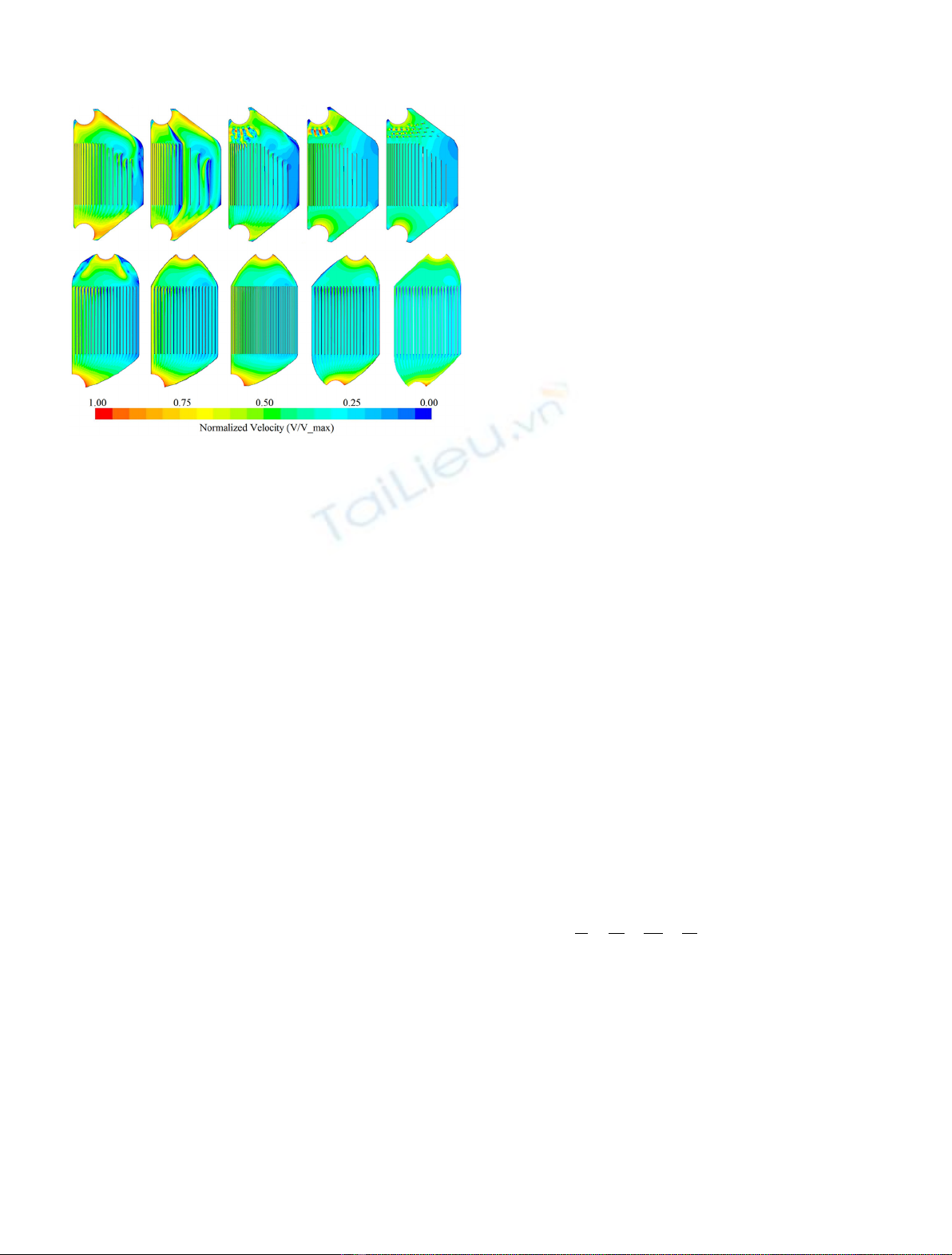
local freezing. Besides, the uniformly distributed mass flux
is preferred in this study to control the temperature drop
and to obtain a smaller temperature gradient in all
directions. As can be seen from Figure 2, there is a
uniformly distributed velocity profile along the channel
cross-section in the final design.
In addition to the flat plate geometry, design studies
were carried out for the corrugated plate. 2D CFD analyses
were performed for corrugated plate. The distribution of
the flow within the channels and the temperature behavior
were investigated. Different combinations of channels have
been studied and the effect over the flow distribution and
temperature profile is examined. Groove depth, groove
opening, channel width and fluid velocities were changed
parametrically. Figure 3 shows the velocity distribution
and temperature profiles of several geometric configura-
tions. The whole system is shown to clearly see the
temperature change amounts, while a small part of the
system is shown to see in detail the velocity behavior. In all
cases, the mass flow rate is the same as each other.
As seen in the sub-figures, as grove depth (a) decreases,
pressure drop amount decreases; however, temperature
difference decreases too. In that case velocity magnitude is
at low level within the channels. On the other hand, as
grove opening (b) decreases, heat transfer amount
increases; however, pressure drop amount increases too.
It should be noted that, to reach the required temperature
drop amount, the height of the HX will be different in all
cases. So in the case of a smaller grove depth, the system
height will increase and also pressure drop amount will
increase too. Besides, in the case of smaller grove opening,
local freezing may occur due to the stagnant flow near the
plate wall. However, this effect may prevent the plate from
the salt corrosion.
After 2D studies, 3D CFD analyses were performed for
a small part of this geometry. The curved structure of this
geometric design made it very challenging to create the
mesh model. Velocity and temperature distribution profiles
were also investigated with 3D CFD analyses. For the
corrugated design, there is no spacer or supporter between
the plates. Since the grooves contact each other in the
opposite direction, they serve as supporter at the same
time. However, stagnation regions will occur around these
contact points. Due to the occurrence of stagnant regions
(and also freezing regions), flat plate model is adopted as
design geometry.
3.2.1 Zero-dimensional modeling
Heat exchanger geometry is divided horizontally by a
number of elements (nodes). The expected fuel tempera-
ture drop (DT
fuel
) is distributed to the elements so that
the temperature of each element will change as DT
node
(DT
fuel
/# of elements). In other words, each horizontal
element is not equal in height, but DT
node
between each
element are the same. In this way, the value of the fuel
temperature in each element can be clearly known which
led to easier calculations, however only the inlet node
temperature of the coolant is known. The heat from each
element of the fuel channel is transferred to the coolant
channel.
The energy that the element has is transferred via
conduction and convection heat transfer to the neighboring
channel. In order to achieve energy balance in the system,
the heat transferred from the fuel channel, the heat
received by the coolant channel, and the overall heat
transfer must be equal to each other. Therefore:
_
mfcp;fDTf¼_
mccp;cDTc¼UATDTlm ¼Qð1Þ
equality must be provided for all neighboring nodes. Where
Qis the total heat rate, _
mis the mass flow rate, c
p
is the
specific heat capacity, DTis the temperature difference,
DT
lm
is the logarithmic mean temperature difference, A
T
is
the total heat transfer surface area, and Uis the overall
heat transfer coefficient. Lower indices m,fand crepresent
the material, fuel and coolant salt, respectively.
The logarithmic mean temperature difference is defined
as,
DTlm ¼DT1DT2
ðÞ=ln DT1=DT2
ðÞð2Þ
where DT
1
=T
f,inlet
T
c,outlet
and DT
2
=T
f,oulet
T
c,inlet
.
The overall heat transfer coefficient is calculated as,
1
U¼1
hf
þtm
km
þ1
hc
þRfm þRcm ð3Þ
where hrepresents the convection heat transfer coefficient
and it can be calculated using several correlations such as
the original Dittus-Boelter correlation or Gnielinski
correlation [24]. k, t
m
and Rare the heat conduction
coefficient, material thickness and the thermal resistance,
respectively. Lower indices fm and cm represent the fuel to
material interface and coolant salt to material interface,
respectively.
So, using equation (1), the unknown temperature of
each coolant nodes can be calculated with starting from the
coolant inlet. The element heights which can give the
Fig. 2. Velocity distribution of 2D parametric studies for flat
plate (plate height is about 1.5 m and width is 0.7 m).
U. Köse et al.: EPJ Nuclear Sci. Technol. 5, 12 (2019) 5


![Ngân hàng trắc nghiệm Kỹ thuật lạnh ứng dụng: Đề cương [chuẩn nhất]](https://cdn.tailieu.vn/images/document/thumbnail/2025/20251007/kimphuong1001/135x160/25391759827353.jpg)