
many installers and customers
are finding that physical
networks designed, installed
and tested to the current Cat 5e
or proposed Cat 6 standards
simply won’t work properly
at 100 Megabit Fast Ethernet,
let alone at Gigabit speeds. Independent Management
Consultant Philip Turtle explains some of the reasons
why this is happening and how one manufacturer seems
to have come up with the solution.
There have been numerous reports during the latter half of
1999 about Cat 5e and “proposed” Cat 6 systems being
installed and passing category testing. Yet when presented
with real network traffic they have failed to pass data
sensibly at all, even though the link lights on the network
interface cards (NICs) are “on,” both on the PC and the hub
or switch.
The practical solution in many cases has been to switch the
100 Mb/s NICs from Full Duplex to Half Duplex, effectively
halving the theoretical maximum bandwidth to 50 Mb/s
and in fact, taking the practical bandwidth much lower.
It’s all about radio waves.
As a teenager, I was a keen ham radio practitioner and built
a VHF radio station operating on the “two meter” band at
frequencies around 144 MHz. Why do I tell you this?
Because Cat 5 systems use 100 MHz rated components and
cable, Cat 6 uses 200 MHz—both very close to my radio
station frequency.
To move signals of that frequency around efficiently within
my transmitting station needed what can only be described
as plumbing transmission lines made out of thin copper
pipes and ceramic insulators—the alternative being
expensive, specially constructed, but very high loss, coaxial
cable. Yet here we are twenty years later happily shoving
similar frequencies down twisted pairs without really
thinking about the physics involved!
Three factors about radio frequency signals are very
important in understanding our problem:
1. They become attenuated very rapidly in a transmission
line system such as our twisted pair, and the power loss
increases with both frequency and line length. So the
signal you get at the receiving end is much, much less
than you started with, a mere 0.005 watts out for every
one-watt you put in at Cat 5 limits.
2. They treat every wire as an antenna radiating energy
into other conductors and receiving energy from them,
too. Just think, you are trying to receive a signal which
is only five thousandths of the high power signal in an
adjacent wire, a fantastic recipe for the interference we
know as “crosstalk.”
3. They reflect or bounce back quite dramatically off any
“discontinuity” that gets in their way, and any poor
connections and impedance change or “mismatches”
along the way prove to be very good reflectors. Every
bit of power that is reflected doesn’t get to the far end,
reducing our power received to even less than five
thousandths of what we put in. And if that’s not
enough, the reflected signal interferes with and distorts
the signal which is going in the correct direction and
can often turn a “zero” into a “one” or vice versa.
Attenuation, crosstalk, reflections
and digital signal processing.
Without the wizardry of digital signal processing, high speed
data over twisted pairs just wouldn’t work. If you look at
figure 1, you’ll see how the signal goes in and how it comes
out, and that it is unrecognizable. The trick is that most of
Improving Bit by Bit.
AS DATA
RATES
RRIISSEE,,
KRONE: 800-775-KRONE www.kroneamericas.com www.truenet-system.com.
No part of this document may be reproduced without permission ©2000 KRONE, Inc.
NEXT
NEXT
Figure 1
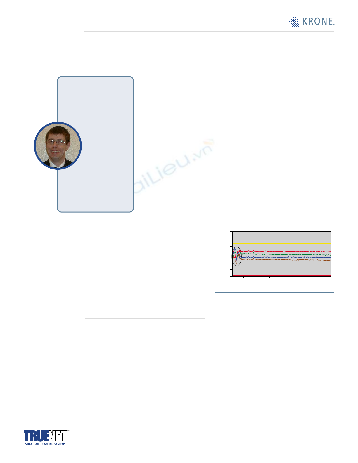
the crosstalk or noise is from a known or predictable source.
In fact, most of the noise (or unwanted signal on the receive
pair of a Cat 5 cable) is generated by the adjacent transmit
pair. So, since we’re generating the transmit signal in the
NIC, it is a relatively easy job to
subtract the interference signal
(which may well be greater than
the signal you are trying to
receive) and recover the weak
signal that we wanted.
That’s great. At least it was when
we were dealing with 10 Mb/s
applications like 10Base-T
Ethernet. Unfortunately as we
get faster, 100Base-T and then
1000Base-T, the effects of
unpredictable noise become
worse. Alien crosstalk signals,
induced from other Cat 5 cables,
become significant; and since we
didn’t generate them in the NIC,
we cannot correct for them. We
call this “alien crosstalk.”
Likewise, reflected power from impedance mismatches is
proving to be an absolute killer and in the specifications,
Return Loss (the measurement for reflected power) is listed
as “For further study,” meaning no one knows what figure
is acceptable and so no one tests for it! And a further
impedance mismatch problem occurs where two mismatch
or reflection points are particular distances apart: standing
waves are set up. (Remember holding one end of a rope still
and waggling the other until it formed a constant sine wave
pattern?) These standing waves can absorb lots of energy
making sure hardly any arrives at the far end!
Reflection points
We have talked quite a lot about reflection points, and
recent lab tests have shown just what a disastrous effect
they can have, but what are they?
In a Cat 5 or Cat 6 cabling system, the obvious impedance
change points are:
■
RJ45 plug to RJ45 jack (particularly if provided from
different manufacturers).
■
RJ45 jack to horizontal cable.
■Horizontal cable where it is severely bent, kinked
or squashed.
■RJ45 jack to patch cord.
■And the worst culprit of all, patch cords.
The Cat 5/5e specifications require every component to have
nominal impedance of 100 ohms, but they allow a tolerance
of plus or minus 15%. This means that at any of the points
we’ve mentioned, there can be an impedance mismatch of
up to 30 ohms (or 30%) and the system is still within spec.
Yet as we now know, reflections are a very serious problem
at higher data rates and a 30% mismatch would have
terrible results. Actually, if it wasn’t for the fact that the
reputable manufacturers use closer tolerances and build
significant “headroom” into their systems, many installations
wouldn’t work at all!
But even though the reputable manufacturers take these
precautions, the result is only assured if you use their
components throughout the system. If you mix and match,
you are absolutely guaranteed to have mismatches. As an
example, one manufacturer might produce cables at
110 ohms (±5) ohms because they’re easier to manufacture
and they’re inside the specification. However, use the cables
in a network with another manufacturer’s 95 ohm
connectors, and you can just see those reflections building up.
Recent lab experiments at KRONE’s Laboratories (with
deliberately mismatched components that were all well
within the Cat 5e spec) showed just how real these
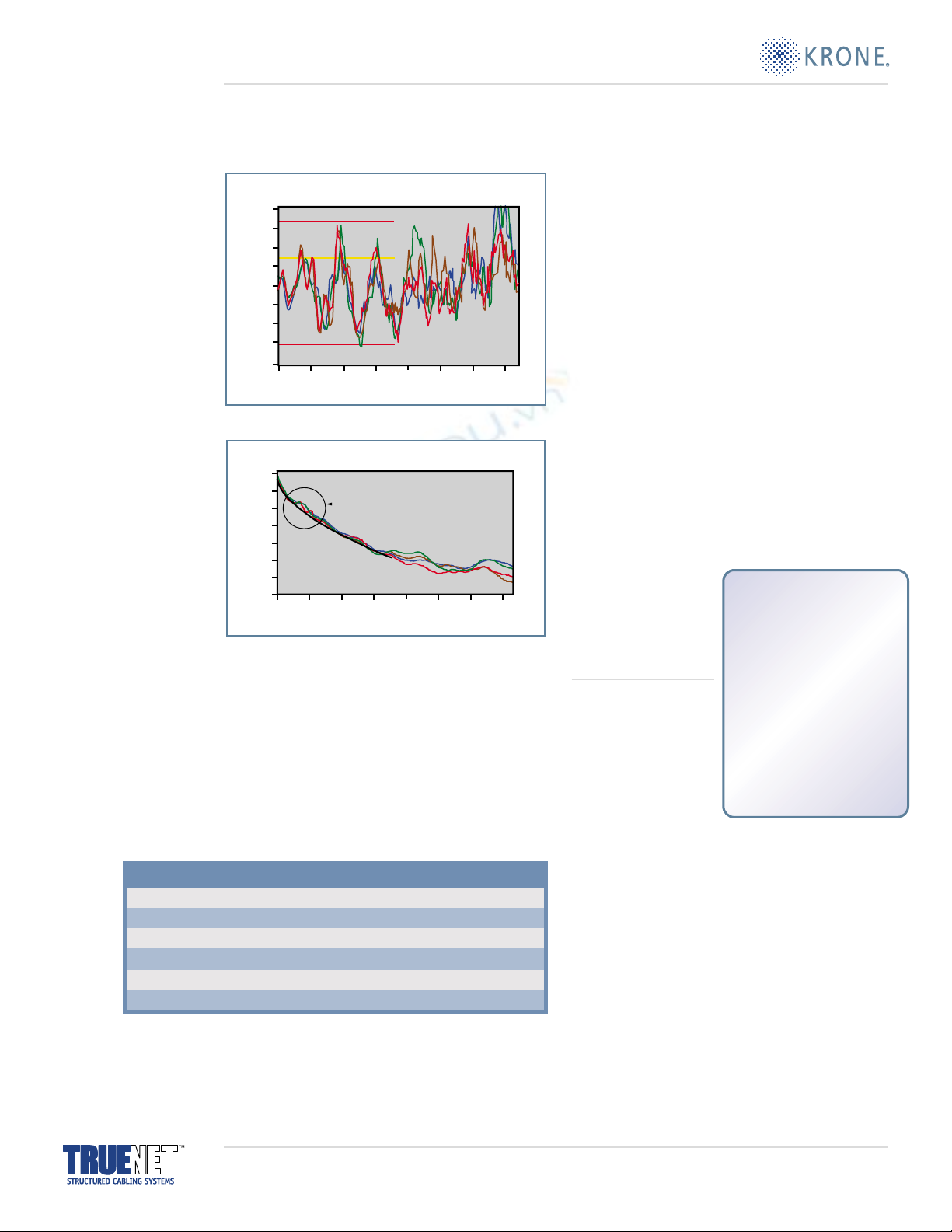
impedance mismatch effects are. Looked at in the time
domain (Figure 2), the system falls within the specification
limits. But you can see the mismatch effect and you can start
to imagine the potential for reflections at the patch and
horizontal cable connection point.
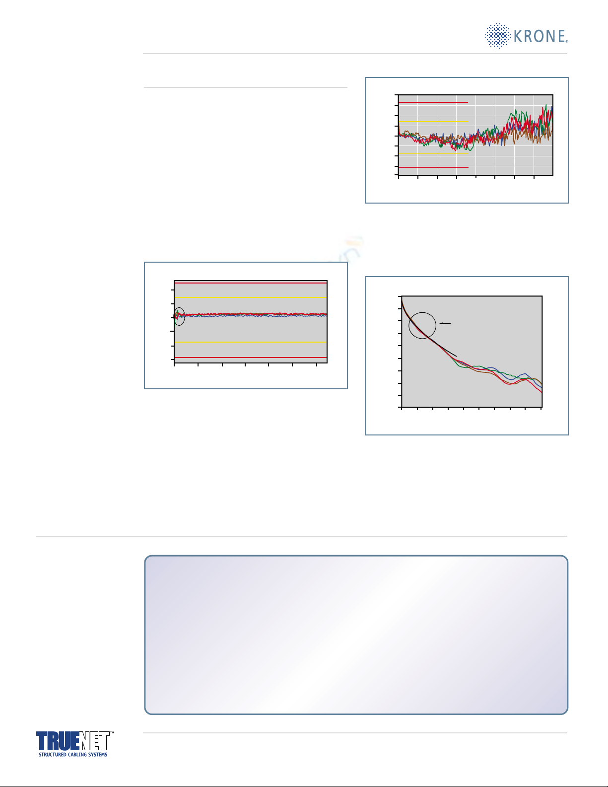
Looked at in the frequency domain (Figure 3) you can see
that the impedance varies wildly far outside the specified
limits at particular frequencies. In fact, you can see some of
the effects of these reflections in the associated attenuation
versus frequency graph (Figure 4), a characteristic not tested
on site, which takes the received signal well below the spec
level at frequencies which correspond to those wild
130.6
121.1
111.7
Mismatch
Patch Cable Horizontal Connection Point
Horizontal Cable
102.2
Ohms
Impedance vs. Distance
92.8
83.3
73.9
0.1 9.9 19.7 29.4 39.2 130.6 58.8 68.5 ......
Meters
BIOGRAPHY
Philip Turtle is an independent
management consultant in the
Internet, communications and
public transport sectors,
as well as a freelance
technology writer.
He is immediate
past national
chairman of the
Institution of Electrical
Engineers’ (IEE) Group and
is actively involved in the
revitalization and
restructuring of the IEE’s
Knowledge Services Division.
Figure 2: Impedance versus distance of mismatched channel
configuration. Note the impedance mismatch occurs at the near
end, approximately 4.2 meters into the channel.
KRONE: 800-775-KRONE www.kroneamericas.com www.truenet-system.com.
No part of this document may be reproduced without permission ©2000 KRONE, Inc.
impedance swings. So it is no wonder installers and users
are having problems on site!
Bit errors
The ultimate effect of all of the problems we’ve looked at is
that bit errors occur. “Ones” arrive as “zeros,” “zeros” arrive
as “ones,” and either way, the chunk of data that we were
trying to send ends up as garbage. Ethernet and other
protocols are thankfully not stupid and can detect when
they receive a packet of garbage. Then they shout back to
the other end, “Sorry, didn’t get that one. Can you send it
again please?” This is okay for one or two garbled packets,
but as the incidence of garbling increases, so do the requests
for retransmissions—and the retransmissions themselves
become a significant but invisible part of the network traffic.
In fact, they quickly become the major part of network
traffic (Table 1). And just for good measure, of course,
in a system with lots of reflections, quite a few of the
retransmitted packets will also get garbled and have to be
retransmitted a second or third time.
In practice it is quite possible to produce horizontal cable
and connectors to the exact nominal impedance of
100 ohms (not some other nominal figure because it is
easier to manufacture) and to control the manufactured
products’ impedance to within a few percent of that 100
ohms. In separate tests, KRONE labs discovered that, in
sending one million bits through a Cat 5 system with only
six ohm variations, some 365,000 (or 36.5%) were actually
being sent again. Of these 365,000 retransmissions, a
further 36.5% had to be sent again and so on. At the end
of the day, Ethernet got the data through perfectly, but it
had to send and receive 1.6 million bits to get one million
correct bits. That meant a reduction in network throughput
of nearly 40%. KRONE engineers claim to have seen far
worse on site. “Field experience has shown that some low
end systems are operating at as little as 4% of supposed
capacity, that’s only 4 Mb/s from a supposedly 100 Mb/s
system,” KRONE Technical
Services Manager
Karl Tryner claims.
Is there a solution?
Yes, radio to the rescue!
But you knew I would say
that. The theory, at least, is
quite simple. If you closely
impedance match all of the
elements of the system,
then the amount of power
reflected is reduced, so is the distortion it causes, and so are
the standing waves that produced all those. The big problem
is with the patch cords because the cable used is flexible, the
geography within the cable changes every time the cable
moves. And therefore so does its impedance. In fact, a
100 ohm patch cable can quite readily change from
85 ohms to 115 ohms in the space of a few seconds as you
re-patch it or run it around the cable management. The only
solution is a new design of flexible cable, which does not
exhibit these wild impedance changes. KRONE has done this,
indeed it is one of the main advances in KRONE’s “TrueNet™
Technology,” which has been demonstrated at trade shows
around the world and with which they are claiming they
can guarantee zero bit error rates on both Cat 5e and
Cat 6 solutions.
% of Retransmissions Data Rate
100Mbps
20Mbps
4Mbps
800Mbps
160Mbps
32Mbps (modem speed)
0%
1%
2%
3%
4%
5%
1.0 28.6 56.3 84.0 111.7 139.3 167.0 194.7
121.1
111.7
102.2
Ohms
Frequency (MHz)
Impedance vs. Frequency
92.8
83.3
73.9
64.4
55.0
130.6
SKIN EFFECT
At radio frequencies, electrical
energy or power does not flow
along the inside of the
conductor, but actually travels
around the outside
as an electromagnetic field.
This is why crosstalk is such
a problem, because every
conductor in the system is a
radio transmission antenna.
Table 1
KRONE: 800-775-KRONE www.kroneamericas.com www.truenet-system.com.
No part of this document may be reproduced without permission ©2000 KRONE, Inc.
Figure 3: Mismatched channel configuration frequency domain.
-0.0
-4.4
1.0 28.6 56.3 84.0 111.7 139.3 167.0 194.7
-8.9
-13.3
Insertion Loss
Deviation
-17.8
dB
Frequency (MHz)
Attenuation vs. Frequency
-22.2
-26.7
-31.1
Figure 4: Mismatched channel configuration (attenuation versus
frequency) shows insertion loss deviation greater than the standard.
TrueNet technology
KRONE has applied my beloved radio theory and produced a
patented TrueNet Technology patch cable wherein the
individual copper strands are somehow glued to each other
to maintain an overall cylindrical shape and the internal
geography of the cable is very closely constrained while
maintaining flexibility. The end result is a patch cable that
has an impedance of 100 (±3) ohms — a factor of ten times
better than the spec.
But you cannot buy KRONE’s patch cable except as made-up
patch leads because they believe that the quality of
termination, strain relief, and testing as a finished assembly
is the only way to be sure of total system performance.
They make them only to specific lengths so as to avoid
known standing-wave wavelengths and their associated
problems. KRONE connectors have always been
manufactured to 100 (±3) ohms so they match the patch
cords well. KRONE’s cable operation has also developed
TrueNet Cat 5e and Cat 6 horizontal cables that are not only
100 (±3) ohms, they also include the neat device of a
helically round central core which significantly reduces the
effects of alien crosstalk.
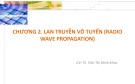
The overall result is a physical layer solution, closely
impedance matched throughout, both in the time domain
(Figure 5) and the frequency domain (Figure 6), which
exhibits such low levels of reflection, attenuation deviation
(Figure 7) and alien crosstalk, that KRONE is prepared to
guarantee the network to be bit error free for five years.
They even test your as-installed network free of charge to
verify the performance warranty.
121.1
111.7
Mismatch
Patch Cable Horizontal Connection Point
Horizontal Cable
102.2
Ohms
Meters
Impedance vs. Distance
92.8
83.3
73.9
0.1 9.9 19.7 29.4 39.2 130.6 58.8
140.0
130.6
1.0 28.6 56.3 84.0 111.7 139.3 167.0 194.7 222.3
121.1
111.7
102.2
Ohms
Frequency (MHz)
Impedance vs. Frequency
92.8
83.3
73.9
64.4
-0.0
-4.4
1.0 28.6 56.3 84.0 111.7 139.3 167.0 194.7 222.3 250.0
-8.9
-13.3
No Deviation
-17.8
dB
Frequency (MHz)
Attenuation vs. Frequency
-22.2
-26.7
-31.1
-35.6
-40.0
Impedance*
Impedance is a measure of the total opposition that a circuit or a part of a circuit presents to electric
current. Impedance includes both resistance and reactance. The resistance component arises from the
collisions of the current-carrying charged particles with the internal structure of the conductor. The
reactance component is an additional opposition to the movement of electric charge that arises from
the changing magnetic and electric fields in circuits carrying alternating current.
The magnitude of the impedance Z of a circuit is equal to the maximum value of the potential difference,
or voltage, V (volts) across the circuit, divided by the maximum value of the current I (amperes) through
the circuit, or simply Z=VII. The unit of impedance, like that of resistance, is the ohm. Depending on the
nature of the reactance component of the impedance (whether predominantly inductive or capacitive),
the alternating current either lags or leads the voltage.
*“electrical impedance” Encyclopaedia Britannica Online
KRONE, Inc.
North America Headquarters
6950 South Tucson Way
Englewood, CO 80112-3922
Telephone: (303) 790.2619
Toll-Free: (800) 775.KRONE
Facsimile: (303) 790.2117
www.kroneamericas.com
www.truenet-system.com
Figure 6: Well balanced channel configuration (frequency domain).
Figure 7: Well balanced channel configuration (attenuation versus
frequency). No insertion deviation.
Figure 5: Well balanced channel configuration
(impedance versus distance).
KRONE: 800-775-KRONE www.kroneamericas.com www.truenet-system.com.
No part of this document may be reproduced without permission ©2000 KRONE, Inc.

![Giáo trình bài giảng dựng audio phi tuyến [mới nhất]](https://cdn.tailieu.vn/images/document/thumbnail/2017/20170926/kloi123/135x160/4831506434587.jpg)

![Đề thi cơ sở truyền tin HK 20122 [mới nhất]](https://cdn.tailieu.vn/images/document/thumbnail/2013/20131013/plitto/135x160/1051381669485.jpg)


![Bài giảng Tổ chức - Cấu trúc Máy tính II Đại học Công nghệ Thông tin (2022) [Mới Nhất]](https://cdn.tailieu.vn/images/document/thumbnail/2025/20250515/hoatrongguong03/135x160/8531747304537.jpg)