
Van Tan Luong, Nhut Minh Ho
LOW-VOLTAGE RIDE-THROUGH
CAPABILITY FOR DFIG WIND TURBINE
SYSTEM BASED ON SERIES GRID-SIDE
CONVERTER
Van Tan Luong*, Nhut Minh Ho+
* Ho Chi Minh city University of Industry and Trade
+ Posts and Telecommunications Institute of Technology
Abstract - This paper proposes a low-voltage ride-
through (LVRT) capability for a doubly-fed induction
generator (DFIG) wind turbine (WT) system. With the
proposed method, series grid-side converter (SGSC) in
which its DC-side connected at the DC bus of the back-to-
back converters and its AC-side connected in series with
line through transformer have been applied, enables to
compensate a voltage response of the system during the
grid faults and to reduce the capital cost. A control
algorithm for SGSC consisting of both positive- sequence
component voltage controllers based on sliding mode
control (SMC) and negative - sequence component
voltage controllers based on proportional integral (PI)
control is performed in the dq synchronous reference
frame. Also, to protect the DC capacitor from its
overvoltage, a braking chopper has been employed. The
simulation results for 2 MW-DFIG wind turbine system
with the voltage compensation at the grid faults are
presented, give as good performance as those without grid
faults.
Keywords - Doubly-fed induction generator, low-
voltage ride-through, series voltage-source converter,
voltage sag, wind turbine.
I. INTRODUCTION
In recent years, renewable energy has been paid a
considerable attention, since the fossil fuels are being
exhausted and environmental issues have become more
seriously. Wind energy is considered as one of the most
important renewable energy sources, where the significant
penetration of wind power capacity may cause some
problems in the power system such as grid instability,
unbalance, and frequency variation [1]- [2].
A doubly fed induction generator (DFIG) is a common
subsystem for large variable speed wind turbines in which
the stator windings are directly connected to the grid and
the rotor windings are served as a power interface between
the rotor windings and the grid through by back-to-back
pulse-width modulation (PWM) converter. The power
rating of the back-to-back converter is typically designed
as 30% of nominal rating of the wind turbine and mainly
depends on the speed operation range of the DFIG. Thus,
deep voltage sags and the stator flux cause a considerable
electrical stress on the rotor-side converter and thereby
increase mechanical stress on the gearbox as well [1 - 2].
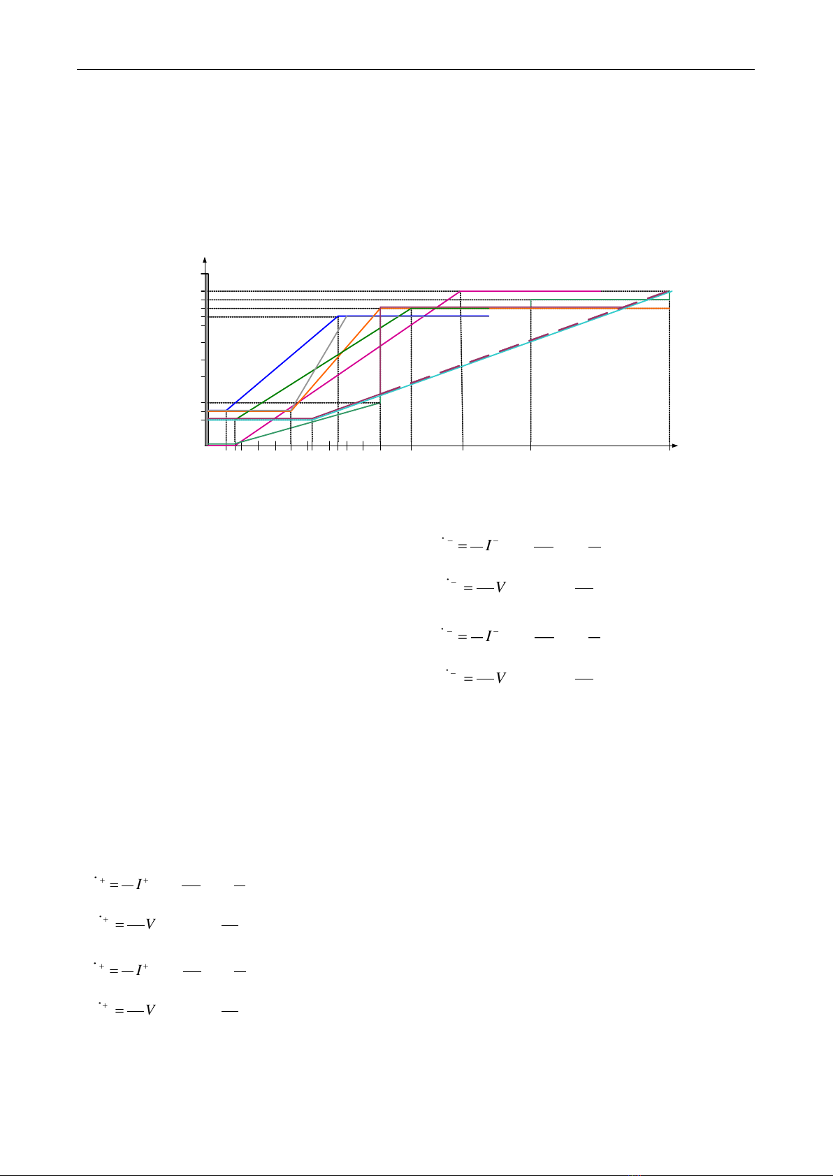
The grid codes require a low-voltage ride-through
(LVRT) capability of the wind turbine system. For several
national grid codes, the wind power systems should stay
connected to the grid for the grid fault conditions, as
illustrated in Figure 1 [3].
To improve the fault handling capacity and protect the
DFIG converter from high rotor current during grid faults,
a crowbar is usually adopted to limit the high rotor
currents and rotor voltages [4]-[12]. In [11], the behavior
of DFIG and the low voltage ride through capability have
been investigated, when an active crowbar is connected
between the rotor side of the DFIG and the rotor-side
converter (RSC) by short-circuiting the rotor temporarily.
It was found that DFIG allows the reactive support to the
power grid during both the normal and grid fault
conditions, and this support is relatively larger when a
voltage controller is used and the wind generator operates
with the light load, instead of constant power factor
control of the DFIG. Also, a strategy of the coordinated
crowbar and braking chopper is suggested to reduce
undesirable fault effects by contributing to the grid voltage
control during the grid fault [12]. The crowbar technology
and the braking resistor do not fulfill the grid codes during
the duration of the activation of the braking resistor or the
crowbar. To satisfy the grid codes, static synchronous
compensator (STATCOM) and dynamic voltage restorer
(DVR) to enhance the ride-through capability of wind
turbines or wind farms [13] – [20]. STATCOM, known as
shunt voltage compensation, is connected in parallel to the
line, while DVR, referred as series voltage compensation,
is connected in series with the line via the transformer.
However, STATCOM can not cope with deep voltage
fault since it is based on shunt compensation. Meanwhile,
DVR, a series compensator, would be much more effective
to restore voltage in strong grid utility. Nevertheless, the
Contact author: Van Tan Luong
Email: luonghepc@gmail.com
Manuscript received: 6/2023, revised: 7/2023, accepted: 8/2023.
No. 03 (CS.01) 2023
JOURNAL OF SCIENCE AND TECHNOLOGY ON INFORMATION AND COMMUNICATIONS 81
LOW-VOLTAGE RIDE-THROUGH CAPABILITY FOR DFIG WIND TURBINE SYSTEM BASED …..
cost of the DVR is so high to solve this problem
practically.
In this paper, the application of a series grid-side
converter (SGSC) that is connected to a wind-turbine-
driven DFIG system to allow uninterruptible fault ride-
through capability of voltage dips fulfilling the grid code
requirements is investigated. With the proposed method,
DC-side of SGSC is connected to the DC bus of the back-
to-back converters, instead of using an additional diode
rectifier, while its AC-side is connected in series with line
through transformer. Thus, this can reduce the capital cost,
instead of using an expensive DVR. Also, for SGSC
control, a positive- sequence component voltage
controllers based on sliding mode control (SMC) and
negative - sequence component voltage controllers based
on proportional integral (PI) control are performed in the
dq synchronous reference frame, from which the SGSC
can compensate the faulty line voltage well. Simulation
results for a 2 MW-DFIG wind turbine system are
provided, gives as good performance as those without grid
faults.
100
90
80
50
75
Germany
TS
85
100
15
20
25
750 625 700 500
150
must remain
connected
1200 1000 1500 2000 3000
Denmark
DS&TS
Italy
<30 kV
GB
TS
Spain
TS
Ireland
-DS
US- FERC
&
AESO Alberta
TS
Ireland
--DS
Hydro
Quebec
Voltage[%]
[msec]
TS: Transmission system
DS: Distribution system
Figure 1. National grid codes [3].
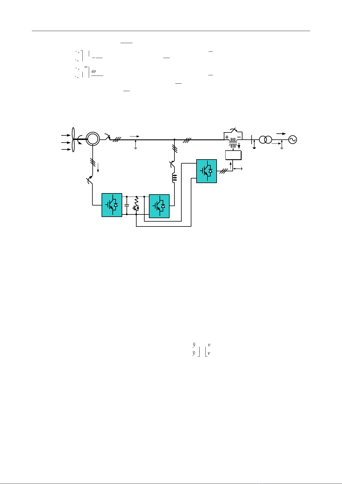
II. SYSTEM MODELING
A single-line schematic of the DFIG with SGSC is
shown in Figure 2. As can be seen in a conventional
DFIG, the rotor windings of the machine are accessed via
slip rings and connected to a three-phase converter
referred to as RSC. The RSC shares a DC bus with a
second converter connected in parallel with the grid and
DFIG stator, referred to as the grid-side converter (GSC).
The shared DC link enables power to flow between the
rotor circuit of the DFIG and the grid connection. The
proposed topology includes an additional converter
connected in series with the line through transformer,
known as SGSC. Also, a braking chopper added to DC bus
is to keep the DC-link voltage at its rated value.
The modeling of the SGSC is briefly described in this
section, in which the components of the positive and
negative-sequence currents and voltages of the SGSC can
be expressed in synchronous d-q reference frame as
follows [16]-[17]:
11
11
11
11
f
cq fq e cd sq
fq fq e fd cq
ff
f
cd fd e cq sd
fd fd e fq cd
ff
C
V I V I
C C C
I V I V
LL
C
V I V I
C C C
I V I V
LL
+ + + +
+ + + +
+ + + +
+ + + +
= − −
= − −
= + −
= + −
(1)
11
11
11
11
f
cq fq e cd sq
fq fq e fd cq
ff
f
cd fd e cq sd
fd fd e fq cd
ff
C
V I V I
C C C
I V I V
LL
C
V I V I
C C C
I V I V
LL
− − − −
− − − −
− − − −
− − − −
= + −
= + −
= − −
= − −
(2)
where
cd
V+
,
cq
V+
,
cd
V−
, and
cq
V−
are the dq-components of
the voltage across the filter capacitor of the SGSC.
fd
V+
,
fq
V+
,
fd
V−
, and
fq
V−
are the dq-components of the inverter
output voltage of the SGSC.
sd
I+
,
sq
I+
,
sd
I−
, and
sq
I−
are dq
components of the grid current.
fd
I+
,
fq
I+
,
fd
I−
, and
fq
I−
are
dq-components of the filter inductor current of the SGSC.
It is noted that the subscripts “+” and “-” denote the
positive and negative-sequence components, respectively.
From (1), a state-space modeling of the system written
in the positive sequence-components is derived as follows:
No. 03 (CS.01) 2023
JOURNAL OF SCIENCE AND TECHNOLOGY ON INFORMATION AND COMMUNICATIONS 82
Van Tan Luong, Nhut Minh Ho
0 0 0 00 1
11
0 0 0 0
0
0 0 1
0 0 0 1
00
1
0 0 0
ef
sq
cq cq
ff
fq fq fq
cd cd fd
ef
sd
fd fd
f
f
C
CI
VV
C
LL
I I V
V V V
CI
C
II
C
L
L
+
++
+ + +
+ + + +
++
−
−
−
= + +
−
−
(3)
Series
transformer
DFIG
Wind
m
SW3
SW4
LC
Filter
Wind
turbine
vs
Grid
Y-Δ
transformer
vg
P
s
Pgrid
vf
iseg
Series grid-side
converter
Rotor-side
converter
Grid-side
converter
SW2
V
dc
P
comp
P
r
v
c
if
SW1
R
Figure 2. DFIG wind turbine system with SGSC and braking chopper.
III. PROPOSED CONTROL
A. Compensation of voltage sag
The reference of the compensation voltage across the
series transformer injected by the SGSC can be
expressed as:
*
,
*
,
*
,
ga presag ga
ca
gb presag gb
cb
gc presag gc
cc
vvv
v v v
vv
v
−
=−
−
(4)
where
,ga presag
v
,
,gb presag
v
and
,gc presag
v
are the voltages
across the low-voltage side of the Y/Δ transformer before
the sag;
ga
v
,
gb
v
and
gc
v
are the voltages after the sag.
B. Control of SGSC using sliding mode control
A multi-input multi-output (MIMO) nonlinear approach is
proposed for the purpose of eliminating the nonlinearity
in the modeled system [18]-[21]. A multi-input multiple-
output system can be considered as:
guxfx += )(
(5)
)(xhy =
(6)
where x is the state vector, u is the control input, y is the
output, f and g are the smooth vector fields, respectively,
and h is the smooth scalar function.
The nonlinear model of the SGSC in (3) is expressed in
(5) and (6) as:
;;
TTT
cq fq cd fd fq fd cq cd
x u y
V I V I V V V V
+ + + + + + + +
= = =
To
generate an explicit relationship between the outputs
1,2i
y=
and the inputs
1,2i
u=
, each output is differentiated until
a control input appears.
( ) ( )
1 1 1
2 2 2
y v u
A x E x
y v u
= = +
(7)
Then, the control law is given as
*
11
1
*
22
( ) ( )
fq
fd
V u v
E x A x
V u v
−
= = − +
(8)
No. 03 (CS.01) 2023
JOURNAL OF SCIENCE AND TECHNOLOGY ON INFORMATION AND COMMUNICATIONS 83
LOW-VOLTAGE RIDE-THROUGH CAPABILITY FOR DFIG WIND TURBINE SYSTEM BASED ON SERIES …….
Where
( ) ( )
22
2
1
22
2
1 1 1
1
0
;0
1 1 1
1
f e f e f
e
fd cq sq sd
ff
f
f e f e f
e
fq cd sd sq
f
C C C
I V I I
C C C L C C C LC
A x E x LC
C C C
I V I I
C C C L C C C
+ + + +
−
+ + + +
+ + + + −
==
− + + + + +
SVPWM
θ
dqp
is
if
vcabc
Positive
sequence
voltage
controller
based on
SMC
Negative
sequence
voltage
controller
based on PI
- θ
θ
dqp
- θ
dqn
+
+
dqs
dqn
abc
dqs
dqs
dqs
dqs
dqs
vg
vg,presag
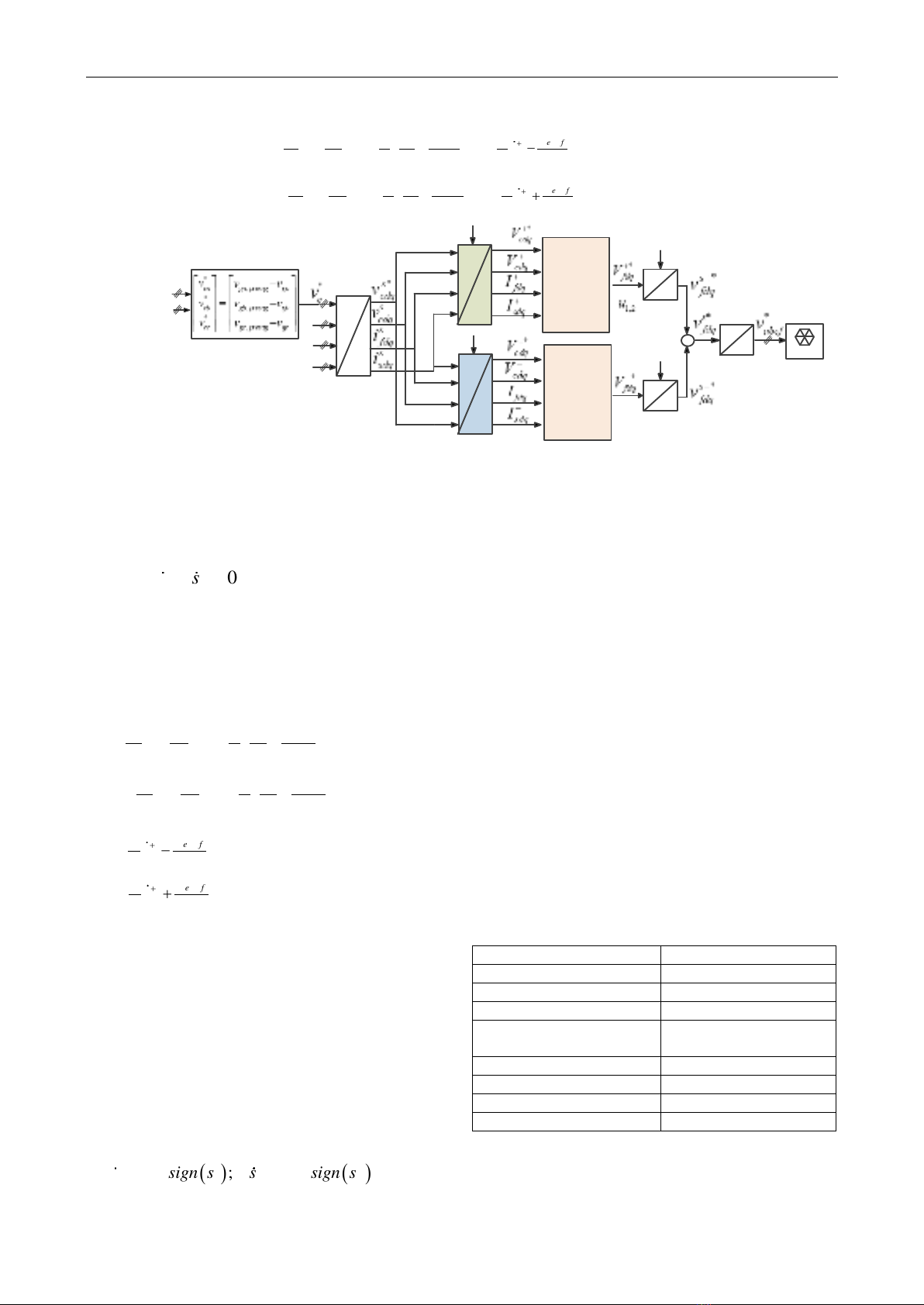
Figure 3. Voltage control block diagram of SGSC
By using a sliding mode control theory, the equivalent
control input can be derived as the continuous control
input that
12
0ss==
yields.
11 11 12
22 21 22
eq f
eq f
uL C v H H
uL C v H H
++
=
++
(10)
Where
22
11
22
21
11
1
11
1
f e f
e
fd cq
f
f e f
e
fq cd
f
CC
H I V
C C C L C
CC
H I V
C C C L C
++
++
= + + +
= − + + +
12 2
22 2
1
1
ef
sq sd
ef
sd sq
C
H I I
CC
C
H I I
CC
++
++
=−
=+
To drive the state variables to the sliding surface
12
0ss==
, in the case of
12
0, 0ss
, the control
laws are defined as
( )
( )
1 1 1 1
2 2 2 2
eq
eq
u u sign s
u u sign s
=+
=+
(11)
where 1>0, 2>0.
The reaching law can be derived by substituting (11)
into (9), which gives.
( ) ( )
1 1 1 2 2 2
;s sign s s sign s
= − = −
(12)
In order to determine the stability and robustness,
Lyapunov’s functions which are presented in [21].
The block diagram of the proposed control is shown in
Figure 3, whereas the components of the positive-
sequence voltages in the dq-axis are separately controlled
by using the SMC. Meanwhile, the components of the
negative-sequence voltages in the dq-axis are regulated,
depending on the PI controller [17]. Then, the outputs of
the SMC control (
*
12 fdq
uV
+
=
) and the PI control (
*
fdq
V−
) are
transformed to the voltage references in three-phase abc
reference frame, applied for the space vector pulse-width
modulation (SVPWM) [22].
IV. SIMULATION RESULTS
To verify the feasibility of the proposed method,
PSCAD simulation has been carried out for a 2 MW-
DFIG wind turbine system. The parameters of the wind
turbine, generator and series grid-side converter are listed
in Table 1, 2 and 3, respectively.
Table 1. Parameters of wind turbine
Parameter
Value
Rated power
2 MW
Blade radius
45 m
Air density
1.225 kg/m3
Max. power conv.
coefficient
0.4
Cut-in speed
3 m/s
Cut-out speed
25 m/s
Rated wind speed
16.5 m/s
Blade inertia
6.3x10⁶ kg.m2
No. 03 (CS.01) 2023
JOURNAL OF SCIENCE AND TECHNOLOGY ON INFORMATION AND COMMUNICATIONS 84
Van Tan Luong, Ho Nhut Minh
Table 2. Parameters of 2 MW- DFIG
Parameter
Value
Rated power
2 MW
Grid voltage
690 V
Stator voltage/frequency
690 V/60 Hz
Stator resistance
0.00488 pu
Rotor resistance
0.00549 pu
Stator leakage inductance
0.0924 pu
Rotor leakage inductance
0.0995 pu
Generator inertia
200 kg.m2
Table 3. Parameters of SGSC
Parameter
Value
Capacity
0.8 MW
DC-link capacitor
8200 F
Inverter output filter
L=0.1 mH, C =1000 F
Switching frequency
2.5 kHz
Series transformer
0.8 MW, 690 V/ 690 V
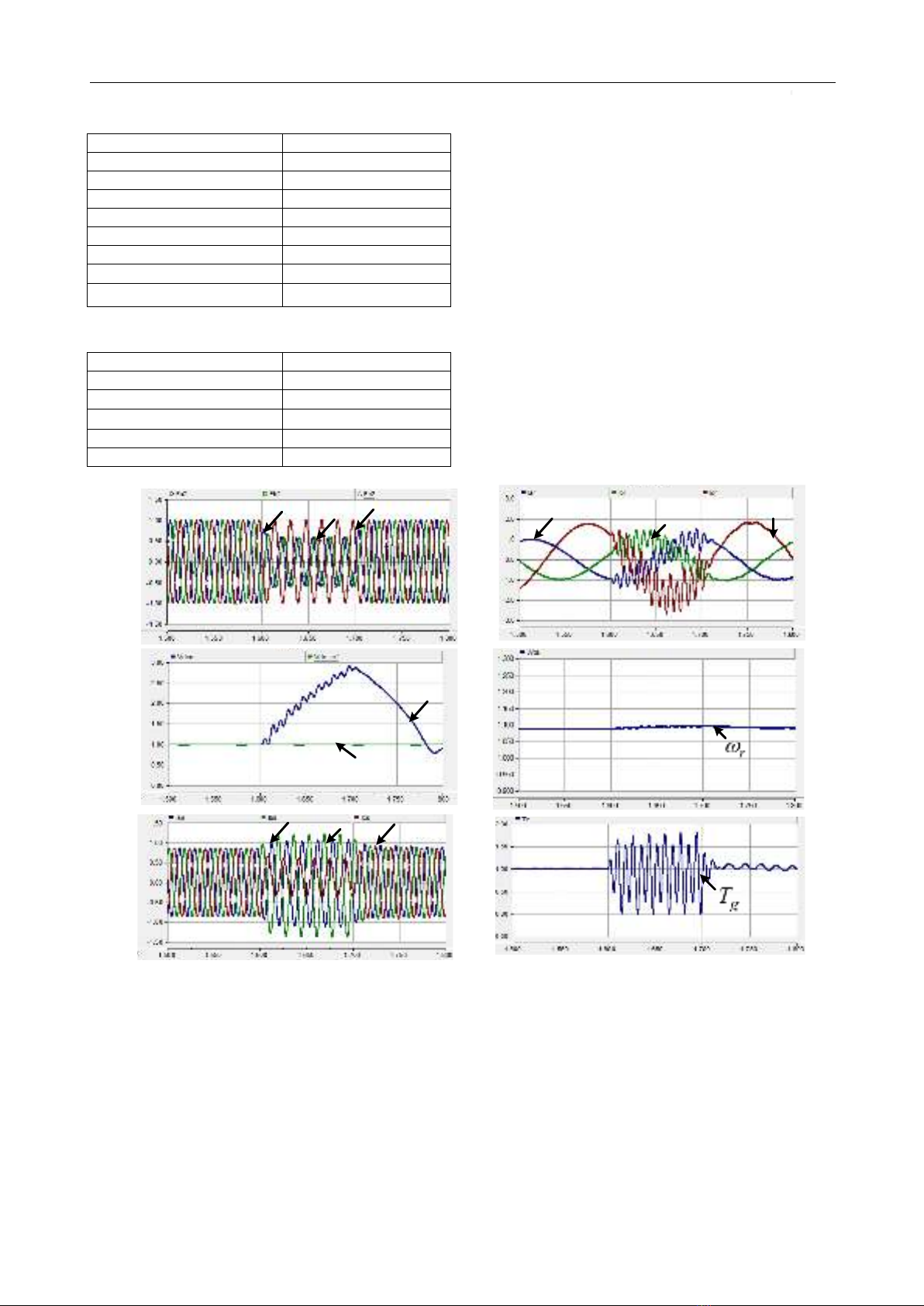
Figure 4 shows the system performance for
unbalanced grid voltage fault without using SGSC
system, where the wind speed is assumed to be constant
(16.5 m/s) for easy investigation. The fault condition is
50% sag in phases A and B for 0.1 s which is between 1.6
s and 1.7 s. When there is the grid unbalanced voltage sag
(
gabc
V
) as shown in Figure 4(a), the negative-sequence
component of the grid voltage exist. As can be seen from
Figure 4 (b), the DC-link voltage (
dc
V
) of the DFIG
converter without using SGSC reaches 2.9 pu, which can
destroy the DC capacitor and the switches of the
converter. Also, the stator and rotor currents (
abcs
i
,
abcr
i
)
are increased, as illustrated in Figure 4(c) to 4(d),
respectively. In this case, the generator speed (
r
), as
illustrated in Figure 4(e) accelerates to obtain the optimal
value for tracking the maximum power point. Similarly,
the generator torque (
g
T
)in Figure 4(f) is also oscillated
under the grid voltage fault.
Figure 4. Performance of DFIG wind turbine system for unbalanced voltage sag (in pu). (a) Grid voltages. (b) DC-
link voltage. (c) Stator power. (d) Rotor power. (e) Stator currents. (f) Rotor currents. (g). Generator speed. (h)
Generator torque.
Vga Vgb Vgc
Vdc
Vdc
*
(b).DC-link voltage (pu)(a). Grid voltages (pu)
(c). Stator currents (pu)
ias ibs ics
(d). Rotor currents (pu)
iar ibr
icr
(e).Generator speed (pu)
(f).Generator torque (pu)
Time (s) Time (s)
No. 03 (CS.01) 2023
JOURNAL OF SCIENCE AND TECHNOLOGY ON INFORMATION AND COMMUNICATIONS 85

![Truyền động điện: Chương 12 [Hướng dẫn chi tiết]](https://cdn.tailieu.vn/images/document/thumbnail/2015/20151209/gaugau1905/135x160/370589692.jpg)
![Truyền động điện: Chương 11 [Hướng dẫn chi tiết]](https://cdn.tailieu.vn/images/document/thumbnail/2015/20151209/gaugau1905/135x160/242078598.jpg)
![Truyền động điện: Chương 9 [Tối ưu SEO]](https://cdn.tailieu.vn/images/document/thumbnail/2015/20151209/gaugau1905/135x160/1518817545.jpg)
![Truyền động điện: Chương 6 [Hướng dẫn chi tiết]](https://cdn.tailieu.vn/images/document/thumbnail/2015/20151209/gaugau1905/135x160/1064960081.jpg)
![Truyền động điện: Chương 4 [Hướng dẫn chi tiết]](https://cdn.tailieu.vn/images/document/thumbnail/2015/20151209/gaugau1905/135x160/346436994.jpg)
![Truyền động điện Chương 2: [Thông tin chi tiết về nội dung chương]](https://cdn.tailieu.vn/images/document/thumbnail/2015/20151209/gaugau1905/135x160/1245913617.jpg)
![Truyền động điện: Chương 1 [Hướng dẫn chi tiết]](https://cdn.tailieu.vn/images/document/thumbnail/2015/20151209/gaugau1905/135x160/1955755336.jpg)


![Bài giảng Vi điều khiển Nguyễn Huy Hoàng: Tổng hợp kiến thức [Chuẩn nhất]](https://cdn.tailieu.vn/images/document/thumbnail/2026/20260316/hoatrami2026/135x160/72211773806757.jpg)
