http://www.iaeme.com/IJMET/index.asp 585 editor@iaeme.com
International Journal of Mechanical Engineering and Technology (IJMET)
Volume 10, Issue 03, March 2019, pp. 585-593. Article ID: IJMET_10_03_060
Available online at http://www.iaeme.com/ijmet/issues.asp?JType=IJMET&VType=10&IType=3
ISSN Print: 0976-6340 and ISSN Online: 0976-6359
© IAEME Publication Scopus Indexed
SIMULATION OF THE DRILLING PROCESS IN
GFRP COMPOSITES USING SYSTEM
DYNAMICS AND VALIDATION BY ANN AND
RSM
Murthy B. R. N and Vijay G. S*
Department of Mechanical and Manufacturing Engineering, Manipal Institute of Technology,
Manipal Academy of Higher Education, Manipal, Karnataka, India
Corresponding author *
ABSTRACT
This paper intends to present the System Dynamics (SD) as a novel method to
simulate the thrust force developed during drilling of GFRP composites. Good quality
holes are extremely fundamental so as to accomplish equally good joints amid
creation of components prepared from composite for better execution. Since the
nature of a drilled hole is subject to material properties and machining conditions, it
is important to think about the impacts of these factors on the nature of hole obtained.
In the present work, the machining parameters thickness of the material, drill point
angle, drill size, drill speed and feed rate are selected to evaluate their effect on the
quality of the hole. Past works uncover the fact that the damage caused to the drilled
hole is primarily due to the thrust force. Consequently it is fundamental to limit the
thrust force so as to accomplish better quality of the drilled hole. The SD simulation
model was implemented through a causal loop diagram. A mathematical equation
used in the simulation was developed utilizing the Design of Experiments (DOE)
technique. VENSIM programming was utilized to create and run the SD model. The
SD simulation results were compared with Artificial Neural Networks (ANN) results,
Response Surface Methodoly (RSM) results and the experimental results. A decent
agreement was seen between SD, ANN and RSM results.
Key words: System dynamics, GFRP drilling, Thrust force, Artificial Neural
Network. Cite this Article Murthy B. R. N and Vijay G. S, Simulation of the Drilling
Process in Gfrp Composites Using System Dynamics And Validation By Ann And
Rsm, International Journal of Mechanical Engineering and Technology, 10(3), 2019,
pp. 585-593.
http://www.iaeme.com/IJMET/issues.asp?JType=IJMET&VType=10&IType=3

Simulation of the Drilling Process in Gfrp Composites Using System Dynamics and Validation by
Ann and Rsm
http://www.iaeme.com/IJMET/index.asp 586 editor@iaeme.com
1. INTRODUCTION
In the fields like aerospace, transport, biomedical, sport goods, etc, we can find the wide
usage of various types of fiber reinforced plastics due to their excellent structural and
functional properties, easy of manufacturing, durability and low cost [1]. The drilling process
in composites involves various parameters such as material properties, drill material, drill
geometry and machining conditions [2]. The execution of these items is chiefly subject to
surface quality and dimensional precision of the hole produced.
As distinguished by numerous scientists, the nature of the hole drilled is primarily
impacted by the thrust force produced during machining. This thrust force is mainly affected
by variables, such as drill geometry, drilling speed, feed rate, and so on [3]. Subsequently,
numerous researchers have attempted to limit the thrust force, through different
methodologies, for example, changing the drill geometry, optimizing parameters, developing
simulations, etc.
Scientists have utilized various distinctive methodologies, while recreating boring, so as
to most likely portray precisely the intricacy just as to compute push powers, torques,
temperatures, instrument wear and so on. Three primary bearings have been embraced
throughout the years.
1. The systematic numerical methodology, where the drilling device is scientifically
described through complicated equations in 3D space and utilized for thorough
geometrical calculations of the drilling procedure. In most of the research
endeavours, 2D anticipated geometry is utilized rather, so as to minimise the
necessary calculations. [3-6].
2. The experimental one, in which extensive amount of experiments were done and
the outcomes are put away in databases so that various parameters can be utilised
for experimentally derived equations [7-11].
3. The numerical approach, where tools like finite element analysis is used, based on
the Lagrangian and Eulerian methods [12-18].
By the literature survey, it is evident that huge contribution has already been given by
many researchers for the advancement of different simulation techniques. In any case, in this
exploration paper we are utilizing System Dynamics (SD) as a simulation tool to build up a
simulation for the thrust force generated while drilling the GFRP composite material.
2. EXPERIMENTAL DETAILS:
2.1 Test specimen: For the present research work, GFRP composite sample specimen was
prepared by hand layup process. As a reinforcement material E glass chopped strands of
density 2590 kg/m3 and modulus of elasticity of 72.5 GPa is utilised. General purpose resin
[GP] is the matrix material and the fiber reinforced volume fraction is 44%. Methyl ethyl
ketone peroxide is the harder used.
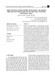
2.2 Drilling process: To conduct the drilling experiments, 3-hub TRIAC CNC vertical
machining centre is used. Kistler dynamometer and the charge amplifier were used to measure
the thrust force produced while machining. Once the essential data is collected in the
dynoware format, the graphs were converted to word format in order to obtain the mean
values of the force generated. The complete experimental set is presented in figure 1.

Murthy B. R. N and Vijay G. S
http://www.iaeme.com/IJMET/index.asp 587 editor@iaeme.com
Figure 1: Experimental set up
Various machining parameters are considered for this study. The details of such selected
factors and the levels of them are presented in table 1. Taguchi full factorial design is used to
decide the number of experiments.
Table 1: Factors and levels.
Factor Level 1 Level 2 Level 3
A: Tool speed (rpm). 900 1200 1500
B: Feed (mm/min). 75 110 150
C: Drill diameter (mm). 6 8 10
D: Drill point angle (deg). 90 103 118
E: Thickness of the material (mm). 8 10 12
3. RESULTS AND DISCUSSIONS:
3.1 ANOVA: ANOVA results of the thrust force is presented in Table 2. As per the table the
factors which are having very significant influence on the thrust force are drill point angle and
the spindle speed. So it is evident that changes in parameters have significant effect on the
cutting force. The table also indicates the effects of combined design parameters. It is evident
from the table that, combinations of Speed* Drill point angle and Speed*Diameter have
significant effect of on the generated cutting force.
Table 2: ANOVA table for thrust force.

Simulation of the Drilling Process in Gfrp Composites Using System Dynamics and Validation by
Ann and Rsm
http://www.iaeme.com/IJMET/index.asp 588 editor@iaeme.com
3.2. Optimization of the thrust force using Taguchi method:
Table 3 represents the response table for data means of the thrust force generated. According
the table, on the basis of smaller is the better concept, the most significant parameter which is
affecting the thrust force is the drill angle, and the next significant parameter affecting is the
spindle speed. Hence to obtain the minimum thrust force it is necessary to keep these two
parameters at lower values.
Table 3: Response table for data means
From the response table for means, the optimum combination of parameters to achieve
low thrust force is: drill angle = 90o, drill diameter = 6 mm, material thickness = 8 mm, drill
speed = 1500 rpm and feed rate = 75 mm/min
3.3 Development of system dynamics simulation model:
The VENSIM model to simulate the thrust force is developed by following the steps listed
below.
1. Drill angle, material thickness, drill speed, drill diameter and feed rate are chosen
as input parameters.
2. Thrust force is selected as the response variable.
3. Each input variable is connected to the output variable in the VENSIM model as
illustrated in the figure 2.
4. To obtain the change in the response variable with respect to changes in the input
variables, a mathematical model (developed using the MINITAB software) which
co-relates all the input parameters with the response, is fed in to the output variable
box.
5. Once the development of the model is completed, it ready to show the changes in
the response value with respect to changes in the input variables.
Figure 2: VENSIM model for the thrust force

Murthy B. R. N and Vijay G. S
http://www.iaeme.com/IJMET/index.asp 589 editor@iaeme.com
3.4 Simulation of thrust force by system dynamics
The thrust force developed for the several combinations of process parameters were found out
by changing the input parameter by moving the sliding bar of the individual variable and the
results were charted. Lastly with the aid of tabulated results, simulation graphs were
developed using MATLAB software. Figures 3-5 shows the simulation graphs of thrust force
for various combinations of input parameters.
Figure 3: Simulation graph of thrust force for various spindle speeds and drill angles.
Figure 4: Simulation graph of thrust force for various spindle speeds and drill diameters
Figure 5: Simulation graph of thrust force for various feed rates material thickness.
3.5. Validation of system dynamic as simulation tool
In order to validate the thrust force simulated by Systems Dynamics, the simulation results
were validated by comparing them with those simulated by two well-known simulation tools,
viz., Artificial Neural Network (ANN) and Response Surface Methodology (RSM).


![Bài tập tối ưu trong gia công cắt gọt [kèm lời giải chi tiết]](https://cdn.tailieu.vn/images/document/thumbnail/2025/20251129/dinhd8055/135x160/26351764558606.jpg)